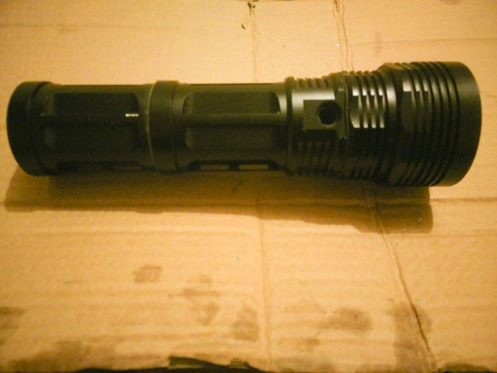
I finally got around to the battery tube. I cut out the center of the tailcap and using a file smoothed and enlarged the non-thread side to fit on a tube segment that had been cut off on the threaded side of the o-ring groove. The ridge was removed with a file, parts cleaned, and the cut off tube was pressed into the new opening in the coupling and attached using jb weld. The segments were assembled to insure contact of the bare alominum ends and to align the battery slots. The scratch in the photo was the result of hacksaw slipping and skipping (perfect for the ‘what did you screw up today’ thread). The flash makes it look worse than it is - I’ll deal with that later. The jb’d joint of the tube segment (the one with the scratch) and spacer will be reinforced with screws in the near future. By mounting the tubes on an unmodified srk head I determined the battery fit is just right with good spring pressure and no rattling when shaken. If all goes well I’ll cut the pocket for the star tomorrow.
Bad luck about the hack saw slip. You could do an OL mod and file grooves and polish them at strategic points just for the looks.
The mod itself though is coming up a real treat.
Really digging the concept and admiring your work. I’m a big fan of press fit solutions, but have mostly used them to make thermal paths. Now you have me thinking bigger. Thank you and keep up the good work on this light.
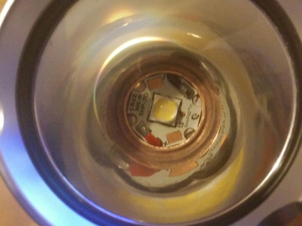
This has been idle for a while but a few steps toward completion. Still need to remove the RJ-2013 style light’s tailcap to extract the switch. When the aluminum was pounded into the center the depth was insufficient to use the reflector as it was. I finally resolved it by removing the reflector’s base but I sanded it down a bit too much. Fortunately the temporary thick o-ring works and the extra space will allow o-rings on both sides of the lens. The copper centering ring is attached to the reflector with a light layer of jb weld and was formed from a piece of 3/4” copper water line. Wires are 20 awg silicone. The mcpcb is affixed with arctic alumina adhesive to help with centering and drilling but will receive screws installed and the adhesive removed and thermal grease applied. The emitter is an xhp70 n2 5a 80+ cri.
Running the same emitter in the Super Courui, I call it my Storm Light, real nice warm tint, cuts thru misty rainy,snowy foggy weather very well! I frosted (diffused) the dome and diffused the bottom of the reflector to the base coat, then lightly stippled the reflector with Hi-Temp Clear, and a UCLp lens, really nice beam now! Very good CRI, I was pleasantly amazed! Great work! :+1:
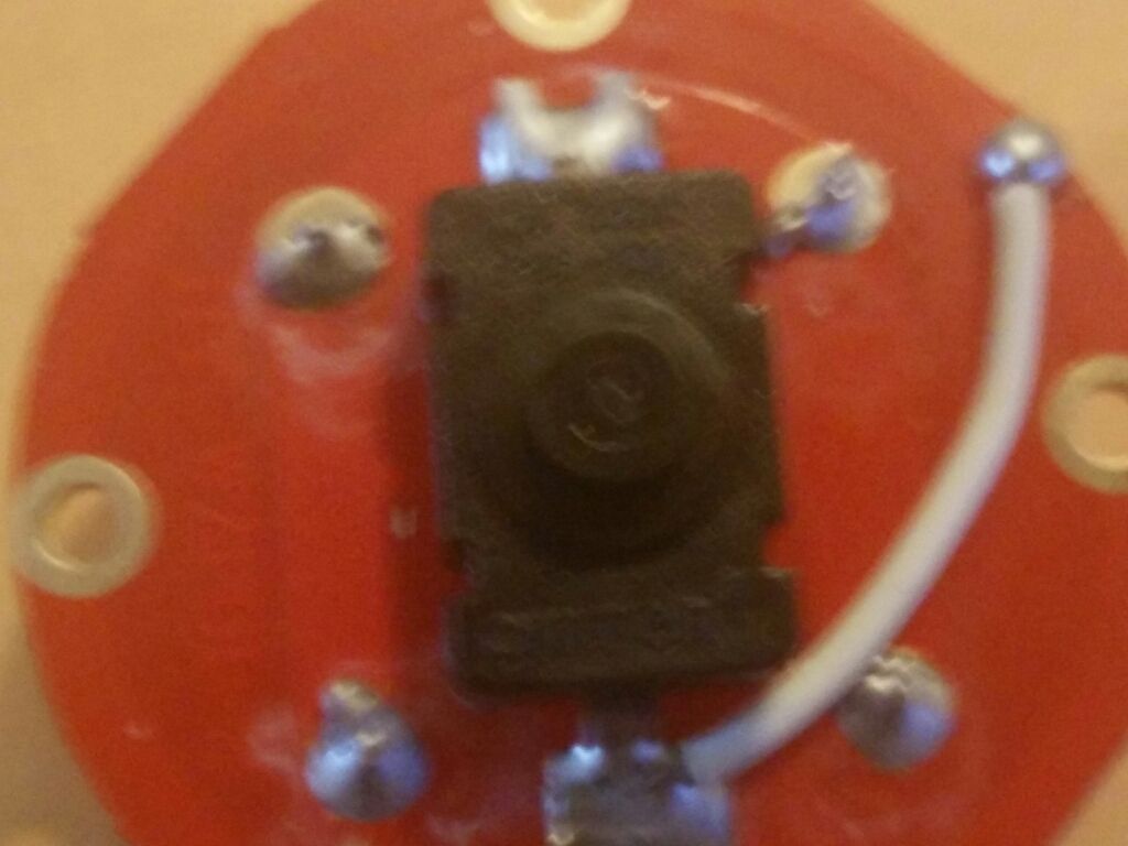
The tail cap of the donor RJ-2013 was securely glued but after a night in the freezer the glue failed and the cap came off with minimal effort. I was pleasantly surprised to find an omten pbs-101.
edit: After removing the contact board I see that it is similar enough to the srk contact board that it will fit. With cells in 2s4p spring bypasses might provide too much current so I’ll leave them as is. The only thing I’ll do to the board is replace the wire with a larger awg silicone insulated wire, touch up a questionable solder joint, and clean up the flux residue.
Driver, switch, and temp sensor wired and installed. Arctic alumina not fully cured and NCR18650Bs charging. Reflector and lens need a light cleaning but i plan to try it out later today and post photos including beamshots after dark tonight. I’ll post photos of beamshots from my Courui D01 for comparison since that’s the only light I have with a similar size reflector. I still need to cobble together a tailcap to accommodate the tailswitch but will test without .
A set of 8x NCR18650s should produce some really good runtimes.
@KawiBoy1428 I plan to use the same method on the reflector but I’m curious how bad the dark cross will be with the reflector still smooth.
Your about to find out, so are we! But it depends on what you deem good acceptable or not? But you do have avenues. I would start with diffusing the dome first, then the bottom of the reflector about 2mm up, certainly if the beam is ringy, then ever so lightly, stipple the reflector if not totally happy with the first 2 steps, IMHO. You can always hit it again it’s amazing what a light spritz of clear can do.
I have just diffused the dome on a few XHP50’s /70’s and in smooth reflectors and accepted the light cross it projected because the rest of the beam was really sweet! I have a XHP50 in a L2 with just a diffused dome that I will not touch even though this artifact exist in the beam, but to me most acceptable. It also depends on the reflector itself right, as in the position the emitter is at or to the reflector, focused, de-focused ect.
I had used and abused this Courui reflector to the point I was going to toss it, but when I changed the XHP50 to a XHP70 in the Super Courui, everything came together! Sometimes you get lucky! :+1:
All the luck to ya, can’t wait to see how this turns out!
Photos delayed. Started out with no light and it took a while to find it was caused by a continuity problem with the tube coupling and now I have to figure out why the mode changes are flakey. Then comes solving the big dark hole and cross in the beam which is otherwise crazy bright with the 2s4p NCR18650Bs. Not ringy, just the cross and hole. Thermal path seems to be effective and on the highest level the head heats up pretty fast. Temperature step down happens at 2 minutes and again about a minute or so later so that’s one thing working properly.
I did a heavy stippling on the reflector I cut down and a light stippling on a reflector from a defiant 3d I cut down. The light stippling helped but there’s still a moderate donut hole in the beam. The heavy stippling eliminated the cross with no hole but it’s pure flood due to the way I cut the reflector. At 60’ it illuminates an area 80’ wide. I also suspect it should be brighter. When the meter I ordered arrives I’ll check the tail current. I suspect it is being limited significantly by the ground path through the tail board screws. If that is the case I’ll clean off the anodizing on the flats near the screw holes and make some copper clips and solder them to the switch side of the tail board for a better ground path. I found a 68mm wide 34mm deep 5° smooth reflector that should work well. I just need to reduce the diameter of the flat at the top by 3mm and remove the 0.8mm thick base and it should slip right in. Pretty much resigned to shaving the dome.
Still cobbling together parts to make a tailcap to fit over the switch.
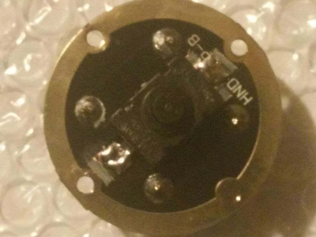
Part of a run pulled loose from the rj tailboard while bending copper to improve ground path. I cut runs on a srk board and transferred the switch. Still minus jumper wire but ready for current tests.
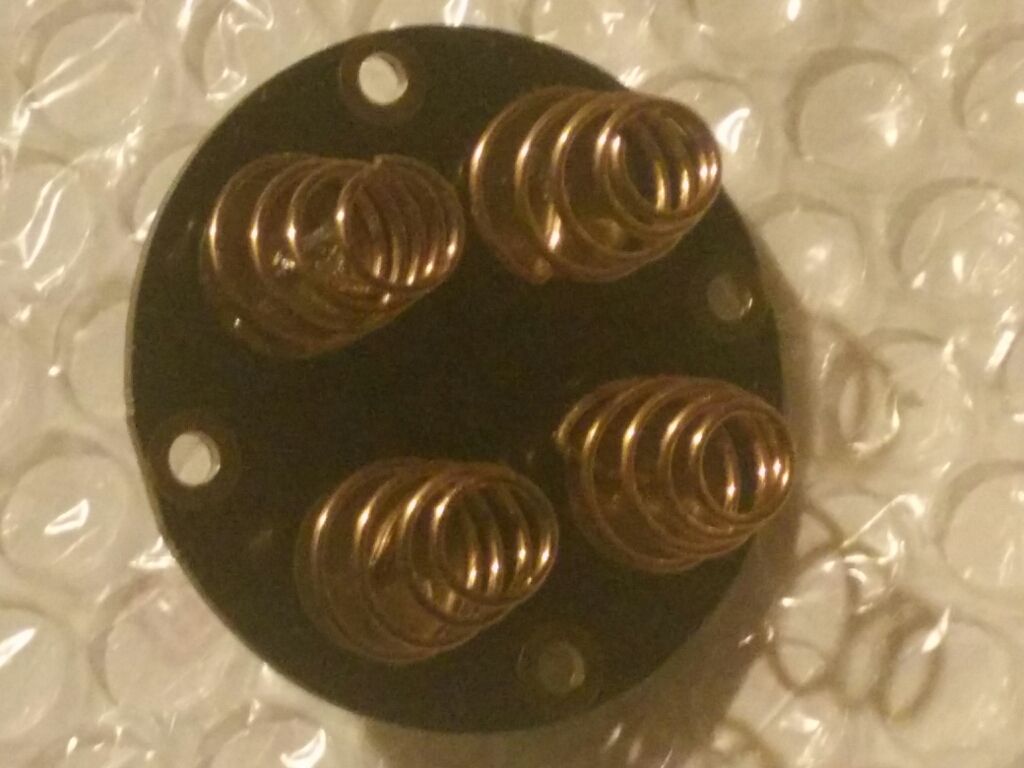
Received the double springs from ebay seller. After a little cutting, bending, and streching they’re mounted on the tailboard
Tomorrow I replace the 7135 on the driver, re-wire, and test tail current. Looking forward to the arrival of the 5° reflectors.
The 5° reflectors were processed through usps isc chicago and are scheduled for delivery by 3/16. Looking forward to seeing what the xhp70 does with a narrow beam reflector. The narrow angle should produce good throw and eliminate the cross and hole.
The reflectors were delivered monday as expected. I reduced the flat on the large end and filed and sanded the base off of one and stippled the other. Unfortunately while doing so I was less careful than I should have been and got debris in the first. Swishing it in a mixture of dish detergent and water, running it under the faucet to rinse, then rinsing again in distilled water left it reasonably clean and without major spots. The one I stippled developed a couple of dark spots from some kind of debris on the reflector when it was packaged - I just unwrapped it and sprayed.
The one I cut and installed did a pretty good job with the cross. At distances of less than one foot from the wall there’s a dark hole with a bright corona but as distance increases the beam changes such that at two feet there are four irregular dimmer regions and at 12 ft there are four slightly dimmer regions in the otherwise bright hot spot. This may improve after I remove the and re-install the emitter - it’s a bit off-center. I removed the star once already and if I do so again I’ll remove the emitter and reflow it to a new sinkpad. Arctic Alumina is a challenge to remove and I don’t wast ro re-use the star after removing AA from it twice. When this happens I’ll mount the star on a 3” dia piece of aluminum rod and test the emitter current. With 16awg wires to the emitter and 2x 18awg wires on the tail board it should be getting plenty. That will have to wait until the paste solder I ordered arrives. I also ordered four more of the reflectors. I thought of a way to do the modifications without getting debris inside if I do two at a time. The stippled one will serve as a form to help create a silicone insert to fill the space between the reflector and head.
I’ll post photos of the first attempt’s beam after the snow’s gone and I have a nice dark night to work in.
New tailcap nearly complete. I cut the threads and a bit of the dividers from the rj battery tube at the tail end, drilled out the center of the srk cap to clear the switch, and jb’d the two together. Using the tail board mounting holes as centers I drilled holes for screws to reinforce the joint. Unfortunately screws prevented the cap from screwing in properly. Pop rivets did a bit better but I’m not satisfied. Looks like I’ll have to make some solid rivets from brass rod. The combined tailcap with the allen head screws tailstands nicely and offers attachment options for overhead use. This tail cap also has a drawback. I need to fab and mount an extension to the switch. I also need to fab a handle to attach toward the front to reduce the load on the tail and improve balance.
The reflector I’m using which has a lip as provides improved heat distribution through the head compared to the original rj reflector that just slipped into the opening in the head. The whole head gets warm in a period when the area ahead of the switch got hot.
After I’ve completed the tail cap I’ll replace the stainless tailboard screws with something better.