I`ve tested tonight L2 / XPL W2 1A@ 6.2 amps agains 1s L2 dded XHP35 E4 1A @ 1.6 amps, both emitters gave nearly the same output, arround or equal at 2000 lumens yet W2 is like 300 000cd and e4 like 215 000
Unfortunately my XHP35 driver fails above 1.6 amps( on a long term base, coil/heat issues) but i guess that at 2.–2.7 amps the XHP will perform kida equal: more lumens yet lower cds : a 2.5 amps driver XHP35 gives like 2500lm/250cds in the L2 host but with a different driver
The lighted tailcap works fine at 8.4V assuming the driver works with it. You just have to adjust the resistance for the higher voltage (takes about twice the tailcap resistance).
Perhaps for you, but I’ve found the UI to be messed up when trying to use the lighted tail cap with a Zener modified FET. I had reduced resistance to 11K ohm on the tail switch lighted board.
I’d venture to say it’s not always going to be a straightforward or easy addition to a light. Don’t know if it’d work on the stock L6 driver at all without some modifications.
Edit: It’s MUCH easier to put a clear boot in place of the black one and install a tritium vial sideways through the post inside the boot. No drain on the cells, easy to find it in the dark.
tryig to work out all the electronics hurts my head, but some of the boys on this forum do it with ease, bastards.
still amazes me as to how far and how complicated some lights have become, seems like the battery and led tech has gotten to the point that only heat dissa[ation is the bottle-neck.Seems as tho the next generation of lights are gonna all posses some form of active cooling.
either way, very interesting.
MRsDNF already built a large one with air cooling holes through the finned pill, the next step would be to install a small MCU controlled fan and link it to the temperature. With a lot of the drivers now going to ATTiny25 and ATTiny85, the storage space is there for programming fan controls I would think, so yeah, just a matter of time…
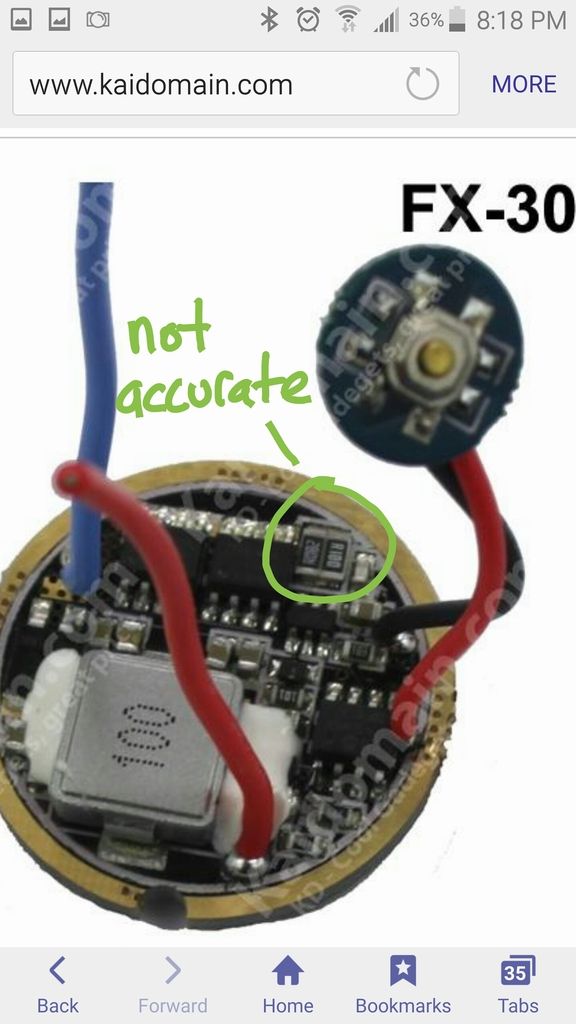
I took off both R082 resistors and put a small piece of wire across the pads. The light still only hits ~5.25A on turbo. I have myself convinced that bridging the pads should give me all the amps the FX30 has to offer. What am I missing?
The bridge isnt good/ the springs are loose/ the spring/battery contact isnt good/ the driver ground isnt good/your MM isnt accurate or your MM cables arent thick enough….so many reasons…
Like TA said: arround 9 amps, pay attention that the driver could mallfunction with this mod( i have several friedalready) especialy on a long term base
I’ve reflowed the bridge a few times, so I feel confident it’s good. The bridge wire is a solid piece of 22AWG. I’m measuring current using a clamp with a 3” piece of 16AWG between battery and tube edge.
Thanks for the heads up on how aggressive the bridge is. I plan to swap the driver out soon anyway, so I’ll probably just abandon this quest for now and focus on that. I want to move to FET based and Narsil for ramping.
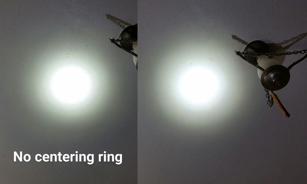
Has anyone here noticed that the stock L6 reflector seems to press down on the red and black wire insulation more than it presses down on the centering ring?
I can remove my centering ring and the reflector won’t go down any farther.
I’ve got an smo reflector now and I’m trying to think of a way to get it lower to improve the focus. Some have swapped to wires with thinner insulation, but why not just cut some small holes in the reflector base to clear the wire and solder blob. Then I can drop the reflector a lot more to see if it helps the focus.
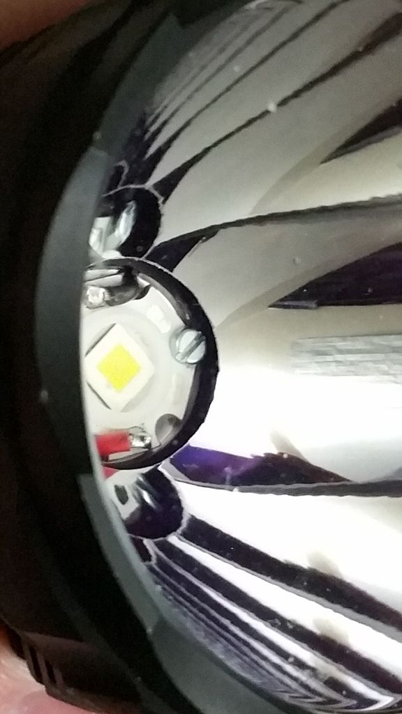
The reflector shoulders and bottoms out on the head I.D. Even shimming the mcpcb board up with a stripped board, the leads/reflector bottom interferes. Relieving or clearing the base of the reflector has to be done, use painters tape to cover both emitter hole and reflector top to keep most of the crap out, clear the interference by filing, sanding or machining, its alot of work, be careful don’t break thru into the reflector surface.
I machine the head to accept a 32mm Noctigon (XP/XHP35 build) or 26mm Maxtoch (XHP70/50 build)
Or cut/ machine the bottom out of the reflector out, and shim the mcpcb to focus…
The stock OP reflector measure 2.6mm clearance between centering ring and reflector base.
I think your over thinking things. There are already tiny fans with temp probes built in that you just feed power to. They will come on at a low level when the probes reach a certain temp and speed up as the temp rises. They are used in computers.
I haven’t seen any tiny enough for flashlight use, but I’m sure they can be built or are already out there somewhere.
In a way, the emitter and mcpcb are just like a CPU. Current flashlight designs have given us these awesome emitters/cpus, but we are still relying on big old solid chunks of aluminum to absorb the heat. That only works for a short time. You can’t cool a computer with that. It’s like we’re still in the stone age.
You gotta have active cooling or maybe use heatpipe technology like laptops use if you wanna run it for a long time. Yeah, now we’re talking.
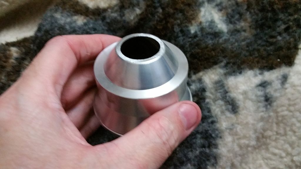
I cut the bottom out of the SMO reflector and fabbed some very thin copper shims to play with the emmiter to reflector distance. I also swapped to new, longer screws to clamp down the emitter for good heat transfer.
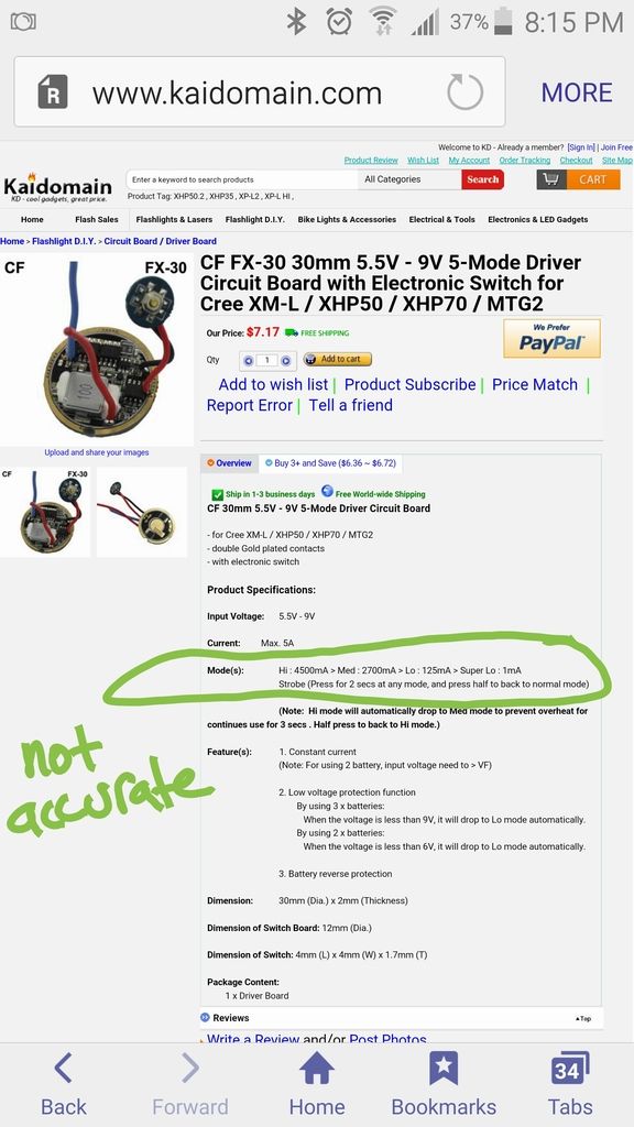
I also wanted to share some info on this new FX-30 driver I got from Kaidomain. Not the Convoy version, the original.
This has a unique interface not described on the website. The tail switch puts it into standby and the side switch only has 3 brightness levels plus a strobe. You can turn the light on and off from the side switch. Very odd. I made a quick video on YouTube showing how it works and went into more details on it.