I’m not seeing P9 listed as a flux bin for the 033B. The highest flux bin listed is P34d22, which is 590-640mW at 500mA forward current. The lowest flux bin in the 276A is P35d21, which is 640-700mW at 500mA.
I know fairly little about UV LEDs, so I could easily be missing something obvious, but I don’t see an advantage to the 033B over the 276A.
There seems to be multiple different editions of the NCSU033B(T) which I cant find a documentation for.
Googling after NCSU033B P9 350 ends up with few links to a datasheet with earlier binning nomenclature.
As for the objective differences between the NCSU033B and NCSU276A these are what I could find is:
NCSU033B has a slighly narrower beam profile 115° vs 130°
NCSU033B has a better thermal resistance 4.4°C/W vs 11°C/W
on the other hand NCSU276A has more raw output
I think these models are not a replacement to each other but rather a compliment.
It’s true that, there could be many applications where the 033B (or it’s bigger brothers sharing the same package size such as: NVSU333A, NC4U133B) would NOT fit the bill due to larger size and higher cost.
Nonetheless, consindering the constructive feedback I’ve received, I’ve readjusted the price.
Thanks for offering these!
I’ll take one. Sent you a pm.
There is one very big difference between these and the newer Nichias:
These older ones have a central solder pad for heatsinking. This is important because UV LEDs are much more heat sensitive than white LEDs. They start to die at much lower temperatures.
The newer ones in turn are much more efficient and thus brighter (but only when they are kept cool).
Please check out this thread here (it’s in German). It shows what happens to the Nichia 276 when it gets too hot inside a Convoy S2+. My light also now has this problem :(.
Thanks for the link. You have a good point there: in addition to a better thermal resistance, the older package can obviously endure a noticeably higher junction temperature
table(table#posts).
|NCSU033B|NCSU0276A|
|Tj=130°C|Tj=90°C|
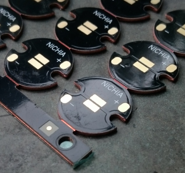
Received some copper and alu. boards for testing how these UV leds fit…
The universal base boards made for both XHP70 & MK-R seem to be a better match than the ones suitable for XHP50 & XHP70. Both are perfectly usable, nonetheless :+1:
I thought so too, but considering that the solder bulges slightly up it worked without a problem. The led got pulled into it’s place once the solder started to flow.
I’ve had (the start) running yesterday without any issues. Then I decided to test the limits…
Hi again, your LED should be on it’s way to Germany as we speak.
I’ve run a test to see if these leds have the same issue…
After pushing the test-unit (the one on the DTP star) to 1.7A i had to stop the test, as I did not have proper isolation of the rest of the lab from UV bombardment.
The die seems unaffected. The star temperature reached around 56°C
Those are pretty cool, and the combination with a readily available DTP board makes them interesting.
Tempted to buy one but $20 for one led, however good the price, still makes me think twice !
That is too good a deal because I got those for free from Simon. But send me your address and you will get some anyway. (and that reminds me that someone else asked for a few of those as well, so I will have some shipping to do )
djozz, PM sent. I’ve ordered some S2+ hosts from GB for modding. Feel free to ship away any S2+ parts you don’t want to keep
The_Driver, wow that was indeed fast. Any plans on how you are going to mount the LED into your host? I’ve modded a 348 with one of these where I just soldered the LED to a rectangular copper bar 2x3x6mm and then glued to the pill…
I’ve got some more playing to do with these today. Any wishes what one should do to a de-domed or, should I say “de-windowed” UV led? :smiling_imp:
Forgot to annotate the photo.
The small die on the anode side is apparently the ESD/TVS protection diode. That fella ensures that this expensive diode does not get zapped by the static. Ain’t that sweet…