Of course your’s is the proper way to do it, rough and functional! But to my defense, my workspace is one small table in the corner of the living room and my wife does not have a comparable hobby (I’m jealous of you!), so my first thought with everything is: how to make it small (even my flashlights are usually small ![]() ). Two years ago I gained some ‘lebensraum’ with a rather large integrating sphere next to that table, which is still hardly tolerated.
). Two years ago I gained some ‘lebensraum’ with a rather large integrating sphere next to that table, which is still hardly tolerated. ![]()
i gotta have one of these, lol… looks like once it is SET UP… its pretty much “automated” the process of reflowing…
You guys are so dedicated, kudos!
![]()
![]()
![]()
Yesterday my new ultra-small ultralight Gophert powersupply was delivered, which I was eying for a year now because it is such a neat thing, this little heatblock was the perfect excuse for buying one.
Its small size suited this heatblock and a small test at the for led reflows perfect 2.8A showed that also functionally it suited the heatblock well ![]()
Fortunately ( :confounded: ) I forgot to switch it off and so it stayed heated overnight. So this morning I found the heatblock and power supply like this:
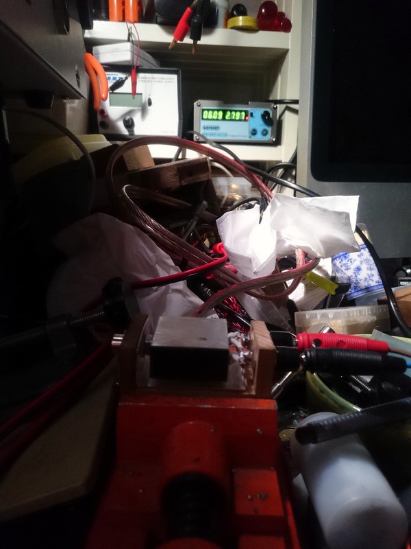
Perfectly unaltered, ps at 2.8A and pleasantly warm to the touch, heatblock going strong at 216 degC. I’m impressed, and glad that it even is forgiving for my forgetting mind.
Huh. Would this cheap little thing work?
EDIT — disappointing, its range of output measures 3.49 to 10.3V
I wonder if there’s an adjustment screw inside if I pop the case open ….
Might still be adequate for heating, I dunno. Time will tell.
Maybe I do really need a better power supply. Yeah, that’s the answer ….
EDIT, June 14th: BG promised to replace the first one with one tested to actually put out 12v.
The replacement has never arrived. I imagine they’re still testing trying to find a good one.
Meanwhile, I bought one of the good Gophert models.
Very cool & creative, thx for sharing!
If two of those heaterelements are wired in series (on my device they are parallel) that thing could be just right and way cheaper than my Gophert power supply which makes the total materials cost for the build next to nothing (but it is less fun than the Gophert ![]() )
)
djozz, why do you want two elements, either in series or parallel? Or was that just how you built it up? I build one prototype with two, and then my second version has just one and it will easily get way hotter than needed.
I’ve been meaning to update you / my thread on this. My latest change (I’ll try to get pics tonight) was two things:
1. I removed the PWM module. It was nice to be able to turn a knob, but it was mostly unnecessary wires and extra components for how infrequently I needed to adjust temperature. Using a small screwdriver to adjust the pot on the power supply works fine for the occasion that I need to change it.
2. I added one of these for $4.99:
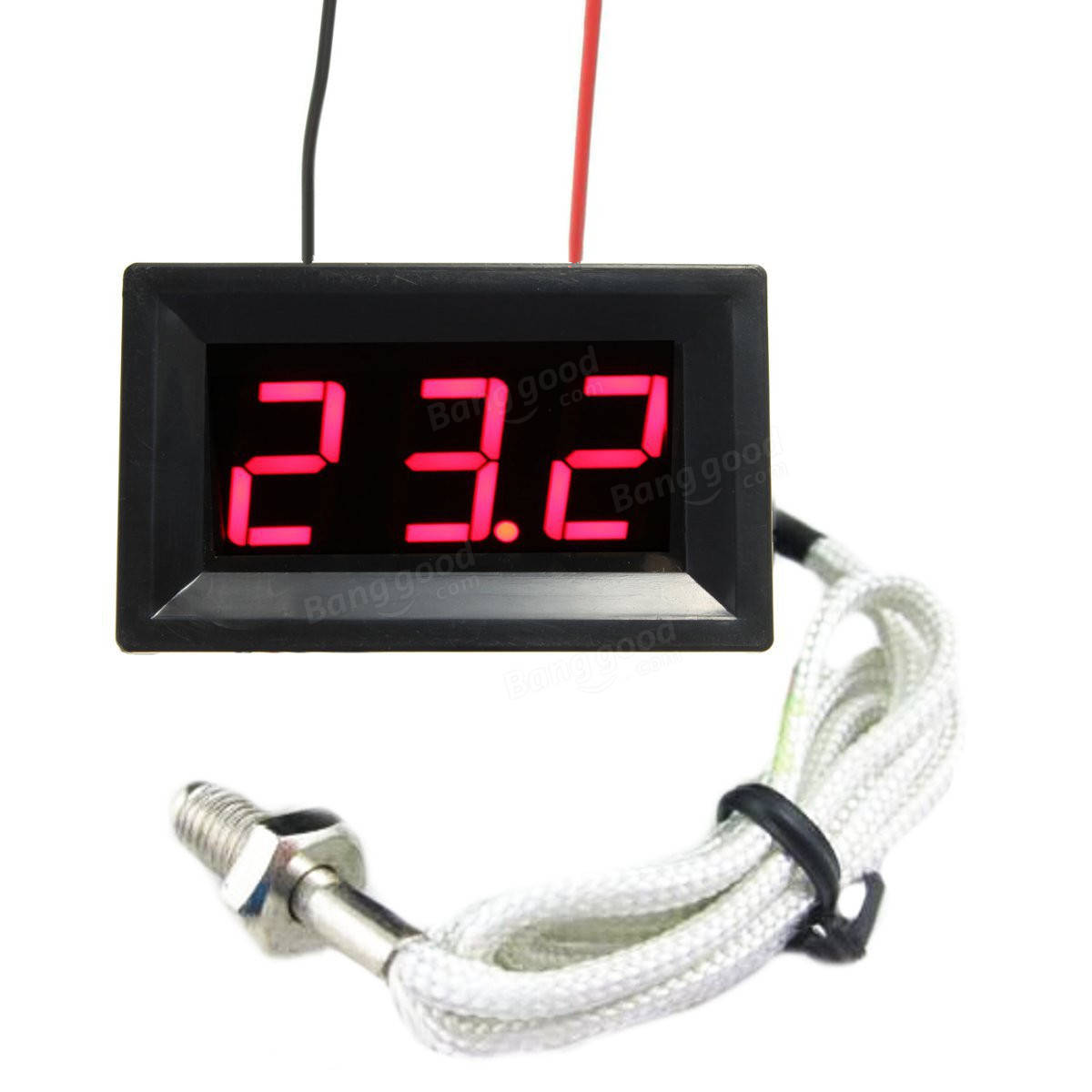
Note that you can buy cheaper thermometers, but they are thermister-based and max out at 110*C, you need at least 180*C for solder reflowing.
I have the thermometer permanently wired to the power supply, but the reflow block (heater element) is on a 5x2.1mm barrell quick connector. So when I’m done reflowing, I can easily unplug the heater, but leave the unit (including thermometer) powered on. That way the block can start to cool down, but the lights on the power supply and the thermometer are still reading - and I can use the lights as my indicator: LIGHTS ON = HOT DO NOT TOUCH!!!
One other thing that I like about my version (that I would recommend for people considering to build their own) is that it does not have any exposed metal other than the top reflow surface. With your version I can predict with 100% certainty that I will eventually someday forget that it’s hot and try to pick it up by some metal part, lol. With the completely encapsulated version, the only hot surface is the top.
Also, your workbench might be messier than mine, congrats. ![]()
Agree on all points, including the workspace. My wife is visibly annoyed every time she looks in the direction of my hobby-corner.
That is a neat little thermometer. With all that cheap but well-working stuff you can go completely wild on making the perfect heatblock for little money. I almost feel like making my version 3 now ![]()
Thanks for spending more of the wifes well earned money djozz and sac. :+1:
Parts will be here in a month or so. Its funny as l dont need a heating plate but who knows. One day. ![]()
After seeing this i had to upgrade my soldering iron hotplate version.
I ordered some printer heating elements and i wanted to order the k-type thermometer but i found something more interesting http://www.ebay.de/itm/172242220658?\_trksid=p2057872.m2749.l2649&ssPageName=STRK%3AMEBIDX%3AIT.
It is a simple 2 point temp regulator that uses a k-type thermocoulpe. And the best it cost only ~8€. Now i have to wait for the parts. Time to work on my Aluminium profile.
The printer heating elements are nice. Cant wait to put all things together!
i know right, these heating elements are designed to work in long time, some printing may takes up to 1 day long
Thanks for the link, very interesting thing, that finishes a complete build. I ordered one too, so that eventually I can make yet another heatblock :person_facepalming:
Excellent find! I will order one as well plus a solder pot from Aliexpress that has a temperature range from 100-550 °C. That should heat up quite a bit faster and no need for a high current power supply.
Does that temp control switch function like I think it does?
Is the DC power supply output routed to the switch, and then the switch output goes to the heater? (Basically, the temp control switch is in-line on the heater circuit?)
If so, can it handle 20W continuous? Possibly more?
Because i do not want to cut a M6 thread for the thermocouple i ordered a new one with a straight 3x15mm end on ebay (http://www.ebay.de/itm/201609250550?\_trksid=p2057872.m2749.l2649&ssPageName=STRK%3AMEBIDX%3AIT).
@sac02
the relay is the limiting part. If i get it right (not 100% clear on the picture) there is this one on the PCB

And if thats the relay the 20W is absolutly no problem!
Damn guys now I want go make one too despite that I don’t need one :D.
As I like to do things a bit differently I would like to add a pid controller. They can be bought for 15 bucks so not expensive and they supposed to be able to controll the temperature perfectly.
I was thinking about using a pc heatsink (you know, those standard small ones) with a fan underneath it to cool it down quickly.
A PID Controller would be way more precise. But i can not find one that uses a thermocouple and that is not so big. They are build for Industrial use. To get one that you normaly build in a electrical cabinet is not a problem and you can get them cheap but they are way to big (100-240V 40A Digital PID Temperaturregler SSR K Thermocouple Sensor Sale - Banggood Deutschland sold out-arrival notice-arrival notice).
@thijsco19
If you want to do things a bit differently and if you want to put the icing on the cake, get a arduino then buy a thermocouple like this (10 Best K-Type Thermocouples For Arduino) and then get a MOSFET Driver Module For Arduino like this (Mosfet-Tubenfahrer Modul für arduino scm Armhimbeerenpi sold out-arrival notice-arrival notice).
Now you are not only capable of controlling the temp very precise you are also capable of using real reflow temp profiles. With preheat phase . . .
And if you want to switch on a fan to cool down the block faster after reaching the max temp you can use a module like this (1 Kanal 12V Level Trigger Optokoppler Relaismodul Sale - Banggood Deutschland-arrival notice-arrival notice).
All relativly cheap stuff. And you can find working code for the Arduino on the net (with a few adjustments). Many people use setups like this to mod a Pizza stofe into a Reflow oven. And most of them are sharing ther code and knowledge.