Efficiency Copper Lumintop Tool, Worm, Maratac, ReyLight

Nice, thanks for the link. So not firmware, but an inductor. Still would like to see the schematic . . . Guessing those are not readily available for obvious reasons. I have seen generic schematics of flyback type drivers before, but I am guessing these are different.

I noticed on the CPF thread you label both emitters as 219B. I guess the different color is just the tint lottery I have heard referred to previously?

I measured my eneloop tonight from my test earlier today, it was at 1.25V. I turned it back on, in less than 5 minutes it was getting noticably dim. Turned it off to compare to Med level,it would not come back on. Must be 45 minutes or so is the max solid output on an eneloop. Interested to do a medium and low run now . . .

yes
here is another example of two leds from the same batch, one is tinted pink, below the BBL, into the magenta spectrum, the other is tinted yellow, above the BBL
the two on the left

here are two 3000k LEDs of different types, large difference in tint (it is quite often that people say they like a certain “tint” when they are really talking about Color Temperature). Even when LEDs have the same color temperature, the LEDs can have very different tint, above or below the BBL

I do not know if differences in tint, or Color Temperature,have a significant impact on runtime, I have not tested for that.
otoh, differences in Color Temperature greatly impact brightness, but again I dont know CCT affects runtime, have not tested. My hunch is CCT has some effect, and tint has less effect… just a guess…

here are 3 N219b LEDs in Astrolux 10180 lights, the far left is slightly yellow/green, the middle is slightly pink, and the far right is more yellow/green than the far left

Thanks for the explanation!

Mine was about dead by the 35 minute mark...

Using ceiling bounce smartphone lux meter it started at 20 lux on high.

At about 20 minutes lux had dropped to 16.

At 25 minutes it was reading 12

And by 30 mins it was register 0 (light was still on, just not enough light for my phone to measure bouncing off ceiling).

Guess I have the bad driver...

yes, sounds like you have the normal Tool driver that is rated for 30 minutes
curious what type of battery you tested, and what type of light and LED… guessing its a Tool of some sort

Copper tool w/ nichia 219b

The Battery was a new eneloop (recharged) from Costco. One of those new Silvery ones if it makes any difference.

thanks, my Copper Tool w Nichia is the same as yours

Below is an unusual one, a Maratac with a large button driver, like my Worm. They run for an hour instead of half an hour, on a regular eneloop… (750mah), as opposed to 900mah for the Pro, not sure of the mah of the costco version, but no matter, I just wanted to make sure you had not tested with Alkaline)

I was planning to put a fet driver in mine tonight, Not sure is the 219b will survive a 10440?

some people use LiIon without changing the driver. I have not heard of the Nichia having a problem

with Cree LED:

I calculate based on that the Nichia would be about med 65 lm, low, 25 lm, high 210 lm.

disclaimer, there is no built in overdischarge protection for LiIon, and the driver is not officially rated for the voltage

So I replaced my driver with one from MTN.

I added some mass to the pill by cutting some chunks of copper from a wire and soldering them to the underside of the pill. There is some kinda coating and the wire didn't want to stick but I scuffed it up a bit and got it hot and it sorta stuck to it eventually. If I do this next time I will sand the coating off the inside of the pill first.

Using Guppydrive Rev2 I selected mode 12 ML - 5% - 15% - 50% - 70% - 100% | No Memory

The driver isn't working well with the LED although it's only a 10440, with a fresh battery the led will color shift and dim. It only really gains brightness up to about medium (50% power). 70% appears the same and it dims and color shifts at 100%.

I may replace with either a 2700k or 3500k 219c 92+ cri, or a 3000k 319a 80+ cri.

Bummer though I really like the tint of the 219b in it. Since I moved slightly off topic. Here is a picture of the top of inefficient driver that was in my copper tool.

Great posting. Now we need to see how efficient one looks like.
Anyone willing to open his light?
Mike

I am Happily surprised to report the latest Maratac Cu w Nichia has a more efficient driver than my CuTool

Maratac w N219b left, CuWorm right:

in the above chart the worm data was from a prior run, so the test was ended sooner than the test I just added for the CuMaratac w 219b

here is an earlier test of the worm and a CuReylight Tool, the new Maratac is more efficient than the Tool in this chart:

test data from two different runs, merged, you can see the new Maratac has a driver that stays Higher Longer

Seemed like it would be good to post this data here also. Data taken on my brass worm. There is discussions on CPF that the performance seen above is not regulation, but just the behavior of a Nimh battery.

Data
two batteries, both at 1.45V. Both provided 1.1A of current to the driver in high mode, slowly increasing, for the first minute or so. Then the current jumped up to 2A and started slowly decreasing. I don’t know alot about Nimh battery characteristics, but I suspect the driver on high for my worm IS regulated, and that the regulation input threshold is crossed and the light performance changes drastically after that.

One more data point - another, newer eneloop that had finished charging in the past half hour. current in high mode started at 1.05A, and slowly increased to 1.35A over about 5 minutes. Then current jumped to 1.95A, I stopped testing. Further confirmation that the Worm is regulating, at least somewhat, early in the eneloop battery life. Also think I figured out how to test this at work simply. Hope to dry run today with the Worm.

One thing I wonder is, if there is regulation, why did they set it where it is? Alkalines will never really regulate with this design, their impedance is too high at these current levels. Eneloops don’t take advantage of this, as their voltage is lower than the set point for the majority of their operating time. And who would design a light around lithium primaries? Finally, if it was for rechargeable lithiums, which the manufacturers say are not compatible, 1.35V is ridiculously below their operating range. It may just be a by product of what ever sort of controller being used.

GOOD TEST SETUP UPDATE - Digital display lab power supply with fairly short wires for leads. I believe the previous testing was distorted due to the current meter impedance.

Brass worm data
Voltage (V) Current High (A) Current Med (A)
1.50.73 0.160
1.4 0.80 0.173
1.3 0.90 0.187
1.2 1.02 0.203
1.1 1.23 0.237
1.0 1.65 0.25?

Sorry jon_slider, not sure how to get a graph and embed it without going through an external website, which is a PITA. Data summary is that the power demanded from the power supply goes up about 25% as the voltage drops from 1.5V to 1.0V. The power increase in medium mode is more dramatic, roughly 2x. But since eneloops are more like current sources, not such a huge deal.

I also note that on the high mode the current drawn from the supply decreases a bit as everything warms up, which I suspect is an artifact of a constant voltage on the LED and LED efficiency increasing as it warms up. But that is just my guess. I did note the current in low mode varied from the low 0.02xA area to a bit above 0.03xA as the voltage decreased. Note the “x” is just a number that I did not record.

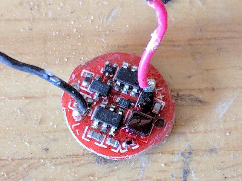
I conclude the Brass Lumintop Worm is regulated in some fashion. I suspect the increase in power as the input voltage decreases is due to conversion inefficiencies of the driver as the current to it increases, but that is just an educated guess. Look forward to seeing if the Maratac rev 4 is the same.

I have tested a copper Maratac AAA and a copper Tool. I have found that for run time on high, they are both comparable to my brass worm, around 40 minutes. On medium mode I found the Maratac to start dimming around 3 hours 40 minutes, while the Worm starts dimming right at 4 hours.

I did not reread this thread, but I think my experience with the copper tool is different than most reported. I purchased my Tool a little over a month ago from GearBest on sale. I bought 4 of them, gave one to my son for a birthday present, sold two others, and have one more still. Likely will sell it also, as I have a copper an brass light already, as well as an aluminum LD01. I personally likey twisties better than clickies.

40 minutes of constant brightness? or 40 minutes runtime? The good drivers will do 40-50+ minutes and hardly drop in brightness at all according to the chart on page 1. The bad driver will be about dead at about around 40 minutes and will slowly reduce in brightness the entire time.

40 minutes of constant brightness. I suspect the difference between 40 to 50 minutes could be batteries, although I have run the Worm twice on high to about 45 minutes before fading. All three definitely hold constant brightness up to 38 minutes, where the Tool started to fade. The Maratac faded around 40 minutes, and the Worm around 45 minutes.

At long last here is a picture of the drivers of the three lights I have:

Left to right is Worm, Maratac, and Tool. I will confirm with words that the details not captured in the photo due to the angle are present in all three boards, primarily two vias that are not visible as they are obscured by the head. One via visible on Tool, one visible on Worm and Maratac, both present on all three.

I have realized that some folks may not understand what a via is. This is not the small coffee packet available from a major coffee supplier. A via is a small hole in a circuit board used to pass electrical signals between the layers of the board. When I look at the Maratac driver (center above) oriented as in the picture above, I see 5 on the left side and 3 on the right side. Look for the small dark dots. If you have a driver in your hand you can see there are two more on the right not visible in the picture above. The lighter colored, areas are copper, and you can see around the edge of the board the actual copper where the light body connects the battery negative to the driver. Most of the board has some masking material on it to prevent solder bridges when the board is assembled. The darker areas of the board are places where the copper has been removed to create different and isolated paths for the current to flow.