nice charger :+1:
Very stylish, CRX!
At Kawiboy: that is some major modding on the Surefire ![]() , and it turned out great! .
, and it turned out great! .
At khas: I forgot about the boosting, of course the led-current is less than the battery current :person_facepalming: .
My mod this afternoon, following XXX-men’s mod, a voltmeter (min. voltage 2.5V, from Aliexpress) built into the Liitokala Lii-100 ($1 ! from a GB flashdeal), that charger is tailor-made for these little volmeters, it has exact the right empty space on the right spot to fit it. I used no glue, just a piece of silicon tailcap stuffed behind the voltmeter was needed to keep it in place perfectly.
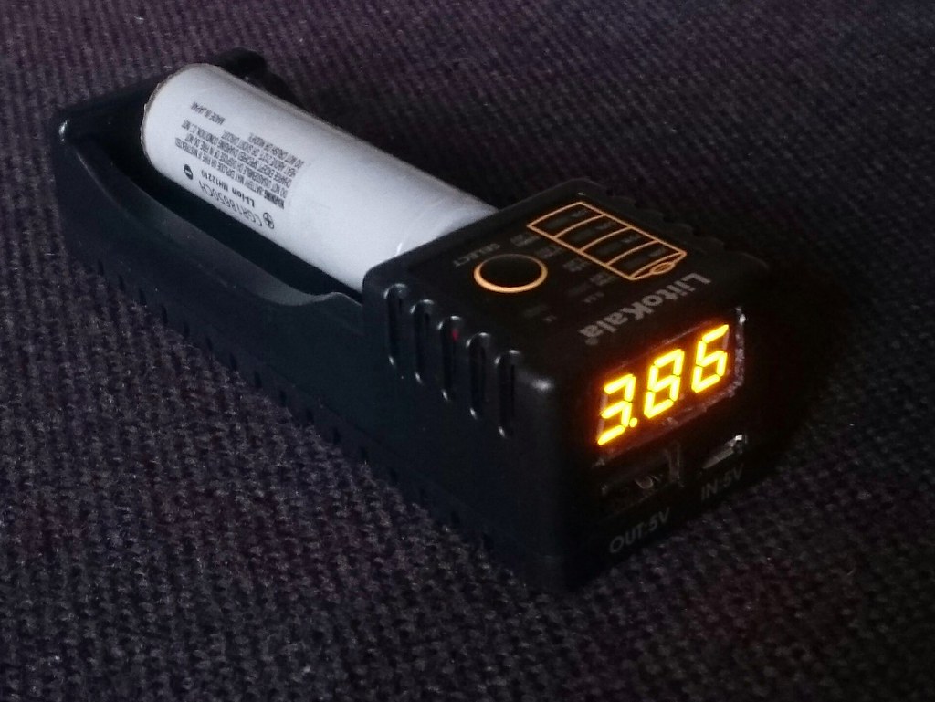
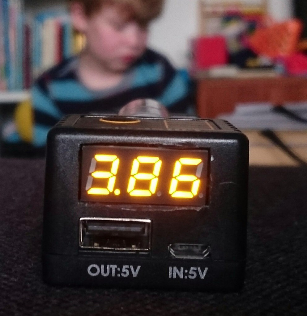
The cut-out is not as neat as XXX-man has made it, but I think it turned out fine. And mine is orange ![]() . My six-year-old has followed the mod from begin to end so he is allowed in the picture.
. My six-year-old has followed the mod from begin to end so he is allowed in the picture. ![]()
Has anyone noticed an effect of the build-in voltmeter on the charger? I find that it does not swap between 0.5 to 1A anymore, stuck at 0.5A. Or did I demolish something? (edit: never mind, it just works, had to hold the button to change charge current instead just clicking it) It is no problem because I will not really use it as a charger (still works fine at 0.5A charging current), just for checking battery voltages.
It seems to read 0.02V low on small batteries, I guess a tiny bit of voltage sag from the power that the voltmeter draws. 18650 cells are spot-on.
The volt meters I received djozz had a small trimpot to adjust the voltage reading.
Ok thanks, have not looked for it but did not need it either because this voltmeter seems to read correctly, the 0.02V deviation on small cells looks like to be caused by the the power draw of the voltmeter itself, 18650 cells have way less voltage sag and read correct within 0.01 V. ![]()
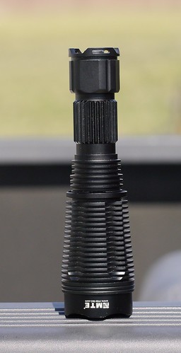
Had a very unusual light come in from a customer with the simple request… “Make it work”. When I got it the star had been removed, no LED of course and the wires from the driver were completely trashed. Someone had tried to replace the LED and it went wrong. This light has a contact plate, as nearly as I can tell it is factory. Someone had installed a free floated FET driver and it was not well wrapped up. So, I tested it and wrapped it in Kapton tape and soldered in a ground wire for guaranteed contact. I replaced the wires and installed a Noctigon with an XM-L2 1A emitter since that should get the best output. The FET was not the strongest in the world, but it did get a bit over 4 amps to the LED and I did not want it to have crazy amps since the lens mounted to the pill was in a plastic or bakelite holder… The light is the MTE H8-1S and is a fixed optical path with several lenses including a very small collumnating lens.
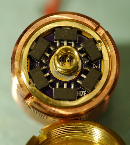
I modded the retaining ring on one of Hoop’s S2+ pills to take the H17f driver. BTW, it is feeding a triple 219b 9080 build! Wonderful tint and I screwed up and did not get any. ![]()
That’s a pretty cool looking flashlight. Certainly worth saving.
Yes, that is why I took it on. The machine work is impeccable on that light. Wish it had been a reflector light or standard optics, would have had a lot more output when done.
quote
Yes, that is why I took it on. The machine work is impeccable on that light. Wish it had been a reflector light or standard optics, would have had a lot more output when done.
endquote
are you sure about that statement?
Yes, glass unless it is extremely high quality with purpose built coatings will eat light. The throw is excellent but the lumens out the front are lacking. I am sure that there are no UD lenses in it. But costs had to be controlled or you would have Canon L series prices.
Even cheap chinese borosilicate glass will still have a transmittance of 95%+
Which is more than most good quality reflectors.
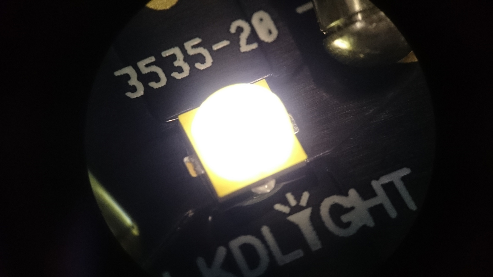
Today I reflowed an XP-L2 on to KD DTP copper board.
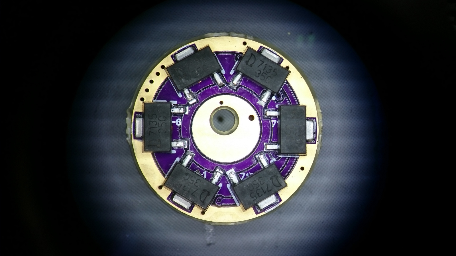
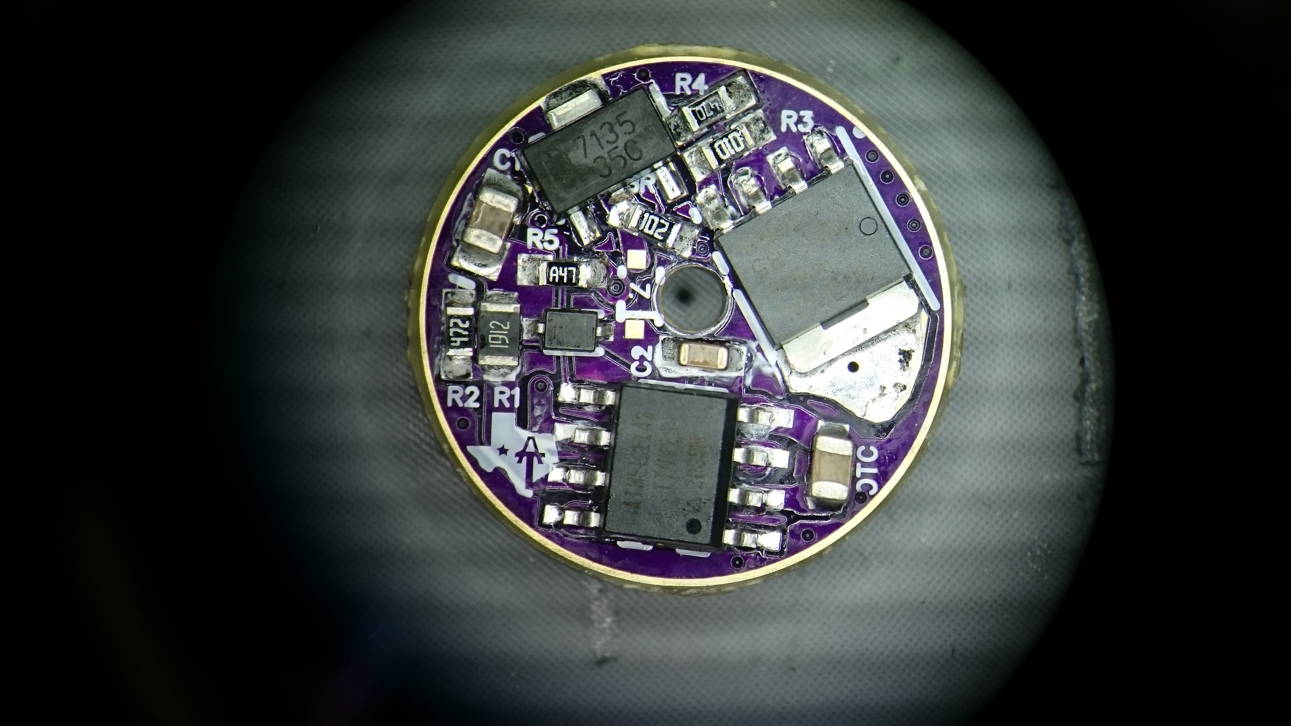
Assembled a Texas Avenger 17mm driver.
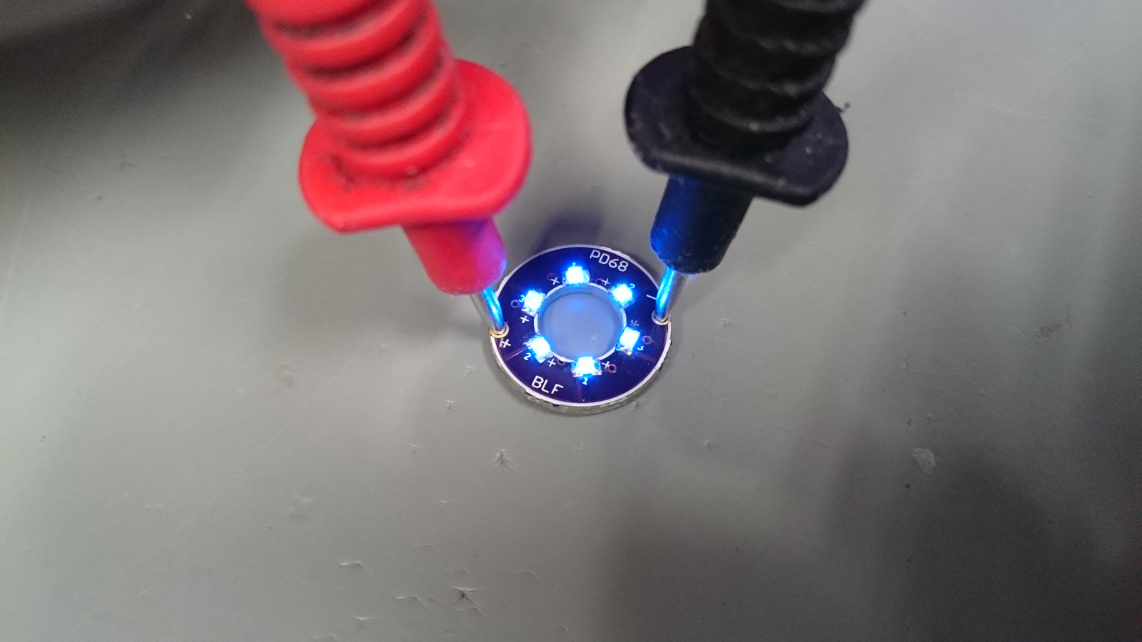
And premade a PD68 lighted tailcap board.
Now just waiting for Convoy C8 host to arrive and put all this into that with AR coated glass and OP reflector.
Showing off your picturing skills, Zozz? They are very nice! :+1:
Just my phone and the microscope at work at the top 3 pics ![]()
BTW thank you!
Nice work on the retainer. How was that accomplished?
I had a conversation via PM with member k-wong, about the ‘fix’ that DEL suggested for the BLF X5/X6 drive and that I have done several times succesfully, that should get rid of the high voltage spikes to the MCU and get rid of the drop-to-moon that occurs spontaniously when entering turbo in a high current triple build.
I described the fix here above in this thread but k-wong was still scratching his head over how it is done and suggested making a video about it.
Well, here is an attempt. I hope it clarifies the procedure.
Of course when doing a video, disaster strikes, you can see C1 unintendedly coming loose together with the plus-wire and then me launching C1 at 1.11 minutes, and I never found it back, so at 1.53 there is a cut in the video (very subtle ![]() ), so that I could search for a new C1 in my stash of parts, don’t know for sure what value the stock C1 was, but now it is 4.7 microFarad.
), so that I could search for a new C1 in my stash of parts, don’t know for sure what value the stock C1 was, but now it is 4.7 microFarad.
After the solder job I checked the driver and it seems to work fine.

I used a sanding drum on a flex shaft dremel and finished with a fine rattail file. I was not sure it would go, but it did!
Yes!! Thanks Jos (and Del), I was ready to buy a bunch of A6 drivers and then I saw your video pop up… I was only kidding when I suggested the tutorial but I’m thankful you did it! Can you provide a link to where I can find the correct 5 ohm resistor to use?
yeah, i admit i love jozz’s pics too…that multiple focus algorithm, whatever… it works pretty sweet…