Mike C drivers: v8 series, ATtiny1634 based.

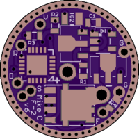
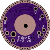
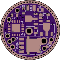
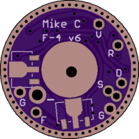
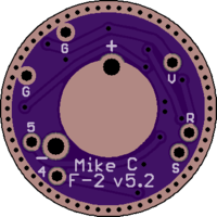
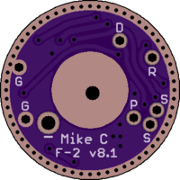
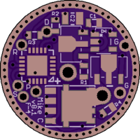
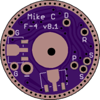
Here are two of my 17mm version 8 series ATtiny1634 based drivers, the F-2 and F-4, suitable for triples or quads.

F-2 is a single sided board with 2 x 7135 and FET: https://oshpark.com/shared_projects/YbI2Xoco

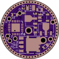
F-4 is a double sided board with 4 x 7135 and FET: https://oshpark.com/shared_projects/xTjUowgj

Any number of the 7135s can be turned on in constant current, and one of the 7135s is PWM:ed for steps in between. Personally I don’t PWM the FET but I put on on a 16 bit counter PWM pin so it can be PWM:ed.
They are compatible with off switch, dual switch and E-switch configurations, and with E-switch only the parasitic drain is about 0.1uF (utilizes the 1634’s low power sleep options). If cells didn’t self discharge, a fully charged cell would last several hundred years. Off time is done with OTSM and measurable off time is about 15 seconds with a 47uF capacitor.

I have basic firmware working, and am working on porting my ATtiny841 firmware which as low and critical voltage monitoring, temperature monitoring, several UIs to choose from, ramping modes, and basically any setting is programmable by button presses (all switch configurations). I’ve also implemented a few different types of user levels, where the lowest level won’t let the user do anything except change user mode (which should be virtually impossible to do by mistake). Firmware will be shared if there is any real interest in these boards. Flashing firmware is done acupuncture style as described in the next post. I use AVRDude which supports the ATtiny1634.

I can also offer built, flashed and calibrated according to preference if there is interest. Price would depend on how many where interested as I normally don’t buy components in larger bulk.

I’ll be doing a giveaway for a couple soon as I have received funds to do it.

A component list for 1S drivers:
R1: 4.7 ohm, 0603.
R2: 0.1 ohm to 1K, 0603.
R3: 3K, 0603.
R4: 100K, 0603
C1: 1uF, 0603
C2: 47uF, 0805.
Diode: 323.
MCU: ATtiny1634 MU (4x4mm QFN package).

I don’t use the voltage divider for voltage readings in 1S lights which is why the value of R2 is flexible. There has to be a resistor there or the OTSM power off detection won’t work. For 1S E-switch drivers the R2/R3 voltage divider isn’t needed at all, but resistors are cheap so I put ’em on so the driver can be used in any kind of light without hardware changes.

This is about as far as I’ll go until there is any interest and someone actually orders bare boards for fully built drivers. I’ve shared boards before on request and in the end no one actually ordered or built any, so this time around I won’t bother with a complete write up unless there actually is some real interest. It doesn’t matter to me weather they are of interest here or not, this is just a hobby for me and I use these drivers in lights I build for myself and other cave/mine explorers, so development will continue regardless.

Other drivers of the v8 series include 17mm with 10 x 7135, 20mm with 16 x 7135, Convoy L4 with 14 x 7135, SRK, TY-T08 (FET + 8 x 7135/A705) and a couple of dual LED headlamp projects. In all cases any number of the 7135s can be turned on for constant current, using PWM on a single dedicated 7135 for brightness levels between the 0.35A constant current steps.

Mike C drivers: v6 series, ATtiny841 based (obsolete and replaced by v8 series in OP, post kept for reference only).

There are the v6 versions of my F series drivers. The v6 boards are on the way from OSH Park so they are currently untested.

The idea behind these drivers is to have a single design that is compatible with single or multiple cell voltages, and clicky, momentary or dual switch setups, all using the same firmware. I went with the 841 as it has the exact same pin configuration as the 84A MCU that I was usings earlier. The 841 is newer and has far better power consumption characteristics, mainly for OTSM but also for lights with only a momentary E-switch. Another benefit as that the 841 has 8 PWM capable pins, 6 can be PWM:ed at the same time.

F-2: Single sided 17mm driver with FET and 2 x 7135s

F-4: Double sided 17mm driver with FET and 4 x 7135s
If the two 7135s on the battery + side are left out, it’s identical to the F-2 except the battery contact pad is slightly smaller. In theory this makes the F-2 obsolete but I prefer the cleaner F-2 if I am building a single sided driver for a light with limited space.

Some technical details about these boards:

OTSM with a 0805 capacitor. I’ve got consistently around 20 seconds of measurable off time with a 100uF capacitor. I’ll test 47uF and 22uF caps later.
OTSM is detected by pin change interrupt. The output of the voltage divider is connected to two pins, one for voltage monitoring, the other for power off detection. In order to keep voltage divider output high enough for pin check I’ve used two 3K resistors. As this only halves the battery voltage the 2.2V internal reference voltage is used for LVP. This setup works very well.
The negative side of the voltage divider does not go to ground, it goes to a pin on the MCU. I do this so I can turn off the divider when in sleep mode to minimize parasitic drain for E-switch only lights.
For multi cell lights I’ve used the LT1761 LDO. It does not leak reverse current so it’s good for OTSM. However, for single cell lights it’s not needed, a SOD323 diode will do and can be mounted on the LDO footprint. I’ve modified the LDO footprint to show how the diode should be mounted:

They are 17.8mm diameter so they can be filed down for snug fits. The QFN MCU doesn’t have accessible pins for flashing, so vias are provided for acupuncture style flashing:

The vias are marked for the pins used for flashing:
V = VCC
R = Reset
G = GND (there is two of them as one is reserved for E-switch)
F = PA4 (SCK)
S = PA5 (MISO) (there is two of them as one is reserved for E-switch)
D = PA6 (MOSI)

Voltage divider output on PA7 and PA6.
Voltage divider negative on PB0.
E-switch on PA5.
FET on PA4.
PWM dedicated 7135 on PB2.
1 x constant current 7135 on PA1.
2 x constant current 7135 on PA2 (F-4 only).

C1 is 0603 input capacitor. I use 1uF.
C2 is 0805 OTSM capacitor. I’ve used 100uF, will test 47uF and 22uF.
R1 is 0603, it’s the same as DEL’s R5 “input resistor”. I use 4.7ohm.
R2 and R3 are the voltage divider resistors. For 1S lights both R2 and R3 are 3K, for 2S lights R2 is 9K, R3 is 3K.
R4 is FET gate resistor. I use 100M.

My full feature firmware won’t be of interest to most but I can share a sort of baseline firmware when I have it ready. It should be enough to get people going. However, there is no point in sharing it if no one actually orders any of these boards. I have noticed that there is sometimes a lot of interest for some things, but once these things are done and shared, no one ends up trying them out. From what I can see I am not alone experiencing this. So, before I commit to making a readable, understandable firmware with all the documentation that is needed for easy understanding, I’ll wait and see if there is any real interest for these boards. Until then I’m just going to save myself the hassle of making comprehensive documentation that has little more interest than for educational purposes.

As usual, these drivers are the results of not just my own ideas and time spent, but of many others like Flashy Mike, Flintrock, fixed it, DEL, Lazy-R-us, Toykeeper, Texas_Ace etc etc… You all deserve credit (and a kick in the butt if you ask my girlfriend).

Reserved…

Very nice Mike. Your setting the pace here. All the best for the project. :+1:

very nice design, thanks for sharing.
Subscribing to thread to see whether the version works. Will probably order afterwards (depending on parts availability)

NICE
Mike C, one of the heavy weight driver devs thanks!
I am anxiously awaiting other heavy hitters and software writers responses here!

I’m working on a baseline firmware to release. Once it’s out I can update with a parts list and so on. Later I can release a full feature firmware for those interested but I suspect the other’s drivers will be more of interest once they are up to speed.

That looks awesome, made it in a 17mm driver! 8k flash, should be able to really make an interesting driver with this one. Extra I/O pins, batt check led’s should now become standard. Can’t wait for this the be ready to roll.

Great work, thanks as usual.

Thanks!

I’m not really involved in the hardware design, but it looks like this opens up all sorts of fun possibilities for firmware. :slight_smile:

If I understand correctly, connecting an e-switch would fill the S hole but it could still be reflashed if someone holds the probe against the filled hole? Also, which 7135 is which? Is the chip in the center the PWM one or the constant-power one? I could see people wanting to put a BAT+ bypass there instead of using the offset hole, but only if it’s the non-PWM 7135 chip which gets sacrificed.

Yes. It would only be one pin one would have to hold if the via is occupied. However, I’ve thought about moving a trace and small signal via, this would make room for another S via so this would not be needed. I’ve waited with making this change as I might want to make more changes once I’ve received this latest design. For development testing with the board outside of a light it’s not an issue though, just have to solder together an additional wire or similar.

The center is on PB2, which I use as for dedicated PWM, but PA1 can also be PWMed.

Why would you want to? In my mind a via for a wire with direct contact with the cell is far better. If I know why, maybe I can re-arrange something in a new design.

Only because it’s physically easier to go through the center of the board than through the edge of the BAT+ pad. There’s often a spring in the way. For example:


It’s harder to do that when the hole isn’t inside the spring:

Aha, ok. I always cut the wire at the end of the via and do a separate spring bypass if I am using a spring. I never really though about doing it that way, just pulling the whole wire through.

If I can’t figure out how to shuffle the F-2’s components around enough I can just design a F-1 for those who want it that way. In any case I need to wait for these boards to show up from OSH Park before I make any changes to design.

Exciting. How many cells do you expect you could go up to in series, assuming the voltage divider and FW is appropriately adjusted? Looks like you are planning on only going up to 2S (based on text in the OP), but was wondering if the selected LDO above can go to 4S.

Do you plan on using one of your spare boards as a pin jig for flashing?

EDIT: I heard that 7135's can't go past 2S, but I've done it before with LDO's. Maybe I was lucky with emitter Vf's close to the battery voltage. I did beef up the 7135 heat sinking in those cases, but I really haven't used those lights much. So maybe they will soon die. Anyway, putting aside the 7135's, I'm wondering what the max number of cells you expect will work.

It looks like, for people who want a driver bypass on BAT+, they could just drill a hole through the middle instead of adding the second 7135 chip. I don’t see any critical traces there. Or they could do a normal spring bypass, or put the bypass on the outside of the spring.

4S. However, my attempts with 7135s on 4S where not successful, so for 4S I have shifted my attention to a 3 amp LDO (LT3083). I haven’t gotten around to testing them out yet though. I have all the parts, I just haven’t taken the time (been more interested in getting the ATtiny841 boards ready.

Do you have any more details on the LDO and design you used to get 7135s running on 4S? I’ve got everything working with 4S except the 7135s.

No. My plan is to have one dedicated development board with stiff pins soldered in place. Then when I want to upgrade firmware in flashlights that have the drivers I would perform some acupuncture like the photo in the OP.

Yeah, but designing a F-1 from the F-2 would be fairly easy. First I’ll see if I can achieve it with the F-2, after I have received and tested the latest version.

Anyone know the via drill size used in that MTN 17DD driver? The size I have used is probably too small as it isn’t designed to fit the whole wire with coating.

Chapeau Mike C
That looks nice
I really like the through-hole programming. :+1:
This might be handy for another driver

Useful for single sided drivers that might be getting firmware updates. Basically all my lights are eligible for firmware updates :slight_smile:

Done. I fiddled around a bit in Eagle and managed to move the BAT+ via almost dead center (it’s a little off). I also made it bigger with a 1.6mm drill size. I had to sacrifice one of the 0805 C2 caps in order to keep both 7135s but I’m pretty sure only one is needed. I’ll upload v5.3 to OSH Park and share it once v5.2 is tested.

You didn’t have to do that… it was already very good. :slight_smile:

My only concern of any substance is whether it’ll be able to fit in common 17mm hosts. But I’m guessing it could have ~0.4mm filed off the edges if necessary? I’d love to hear whether it fits into popular 18650 tube lights, since that size of driver gets used so widely.

To be honest I did it for myself. I hadn’t thought about wiring the LED that way, it’s pretty neat. I also needed a break from coding, so a bit of mucking about in Eagle was welcome.
I changed the via size down to 1.5, but there is enough clearance for a 2mm hole if one wanted to drill it out. I was thinking about putting a hole instead of via, but that would mean a little extra hassle for my lights where I don’t want a driver spring.

I’ve used this same 17.8mm diameter drivers in my S2, S3, M1 and M2s since a long time. I use that diameter so I can file down for a snug fit, although I haven’t had to file anything off but the fabrication panel tabs for the shelfless S3 and M2. Filing all the way down to 17mm would be no problem, there would still be some ground ring left, you would have just hit the holes in the ground ring vias.

Mike C wrote:

4S. However, my attempts with 7135s on 4S where not successful, so for 4S I have shifted my attention to a 3 amp LDO (LT3083). I haven’t gotten around to testing them out yet though. I have all the parts, I just haven’t taken the time (been more interested in getting the ATtiny841 boards ready.

Do you have any more details on the LDO and design you used to get 7135s running on 4S? I’ve got everything working with 4S except the 7135s.

When I get a chance, I'll dig up one of my lights that I did it in and double check that they do work properly. If it does, I'll report back.