making a small batch of Texas Avenger "TA" Drivers fully tested running Bistro or Narsil, Clicky or E-switch, SIR800

Low voltage warning is quite obvious on a DD light, it will get very dim, like <0.5 Lumens on a XHP70 when the batteries get below 2.8V

LVP shuts down the light in any case, LVWarning just reminds you to switch batteries, both is running in Narsil v1.2 fine for 2S
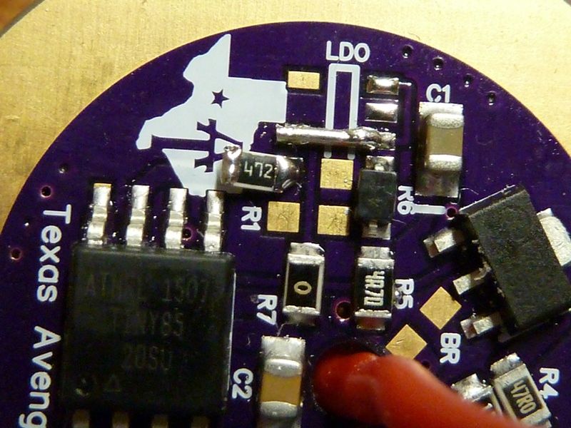
In 2S configuration the MCU does not see the cells voltage from Vcc of the MCU as it is regulated with the LDO
In Narsil v1.2 the LVP is on Pin 7 with a seperate set of resistors, no problem to flash this, but you loose temperature stepdown and indicator LED

in v1.3 and 1.4 he added there a indicator LED, those also have temperature stepdown

he is working very much on Narsil for the Q8, and will look into getting the 2S LVP
if he releases v1.5 I bet there is an option in the code to switch between indicator LED and LVP on Pin 7

it comes down that the Attiny 85 has a limited amount of IO pins, if it had more he would not have to remove the LVP in v1.3

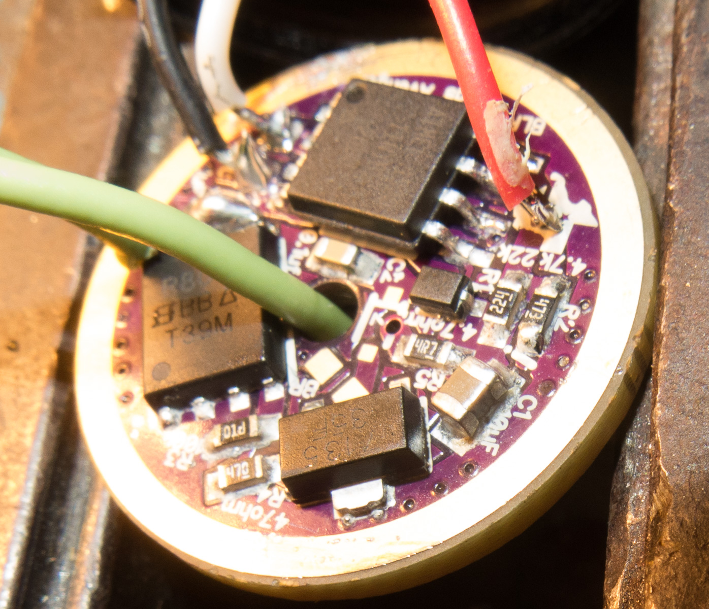
The first 10 driver I soldered with an iron, took me about 35-40 minutes for each driver

This batch i will order solder paste and reflow em
I hope to get below 20 minutes per driver to assemble the driver reflowing

Bistro:flashing and testing Bistro adds another 10 minutes,
but a faulty one eats easily half an hour or more if you have to unsolder the 7135 for example if one is faulty

Narsil: Configuring code for different setups, flashing, testing, add resistors for Diodes and temperature calibrate the Narsil takes about 20 minutes

In both cases its possible to modify mode groups in source code if requested
or configure the driver as you like
It will add a little fee as it takes time

I calculated the prices above with about 10$ per hour just the time to assemble and test,
the first ones will be slower but with that many drivers I can reduce the time

the raw material costs for a 21mm Narsil are about 8$

there is no more parasitic drain on the 1 cell driver than the original Skilhunt driver
The LDO is only for 6V LEDs like XHP50, XHP70, or MTG2, with it the parasitic drain is also really low

just the 6V driver with Zener mod draws a few mA when off
as there are such nice LDO boards i would not recommens anyone a 2S driver with zener diode
a few hundred uA can be used for lighted sideswitch adding the bleeder resistor mid air and solder the LED wire on it

the indicator LED can be configured in Narsil to act as locator beacon, only this will increase parasitic drain, but the 1S driver got in any case LVP ad shuts down when the voltage drops betwenn 2.8 and 3V

you can read the manual for narsil, to see what a rich set of functions it has

the main settings are:
Setting # Function Clicks Defaults
1 Ramping Mode 1=disable, 2=enable; 2
2 Choose Mode Set 1-8 (1-7 is # of modes) – see Mode Sets; 4
3 Moon Mode 1=disable, 2=enable; 2
4 Mode ordering 1= sets low-hi, 2=sets hi-low; 1
5 Mode Memory 1=disable, 2=enable; 1
6 Turbo Timeout 1=disable, 2=30 secs, 3=60 secs, 4=90 secs,5=2 mins, 6=3 mins, 7=5 mins, 8=10 mins; 1
7 Blinky mode 1=disable, 2=one strobe, 3=all strobes/beacons; 3

the optional settings are:
1 Set Moonlight Level 1 - 7 (PWM value); 3
2 Active Temperature Regulation 1=disable, 2=enable; 2
3 Locator LED feature 1=disable, 2=enable; 2
4 Batt/Temp/Vers Ind. LED Only 1=disable, 2=enable; 2
5 Indicator LED Enable 1=disable, 2=enable; 2
6 Power switch modes w/mem 1=disable, 2=enable; 1

added

I also thought about UV hardened glue to fix the position of the SMD parts before reflowing

I have no expirience with it, I guess watch the reflow on my stove and carefully push misaligned parts with a toothpick should work as well

Anyone got expirience with reflowing boards with 0603 parts?
This should make it possible to both sides of the boards reflow in one run

ordered this stuff
http://www.ebay.de/itm/LOCA-UV-Kleber-Flussigkeit-Glue-Liquid-optical-Adhesive-Glas-5ml-TP-2500-Display/302232076414?\_trksid=p2047675.c100005.m1851&\_trkparms=aid%3D222007%26algo%3DSIM.MBE%26ao%3D2%26asc%3D42828%26meid%3Dc011195028cb42a0bb646d450424cdb8%26pid%3D100005%26rk%3D3%26rkt%3D6%26sd%3D381860372429

It’s really nice to see the driver available from an EU source as :+1: well

I would like :
Two 21mm 1s short spring, with Narsil (for two Skilhunt H02)

What version of Bistro is it ? TA’s version or TK’s version.

Skilhunt H02 needs the Narsil firmware as it is sideswitch only
current release is v1.4 for 1S lights
unless you want switch modes by unscrewing thailcap with Bistro

The Narsil driver will be equipped with an 4.7k resistor for the switch LED
the red wire goes to the LED of a resistor soldered to pin 7

this is my modded H03 with narsil 21mm
first try on reflow soldering with 0.3mm solder wire, definately need paste

Ok i would rather have the latest Narsil version with indicator and power LED and temperature stepdown

I don’t think there is switch LED in the Skilhunt H02.

I am thinking of ordering a 17mm 1s with Bistro for a C8, so I would still like to know what version of Bistro it is :wink:

Made 22mm (or 21mm) LDO driver with 0603 resistors. Nothing extremely difficult , you just need to be careful placing the 0603 parts because they are tiny .

It is TA bistro with Triple channel.
Mode groups and hidden modes are different from stock Bistro.

This has all the information and link to firmware

Ok skilhunt H02 has no indicator LED, but you could add one

Thanks, can you please put me down for a 20mm 1S Bistro as well,you don’t need to add the resistor to the two 21mm drivers putting a indicator LED in the switch is way beyond my skill set :slight_smile:

EDIT : 20mm 1S Bistro long spring

an easy way to place an indicator LED is drill 2 small holes through the switch PCB
use some epoxy to glue the wires in there so that the insulation is a tiny bit outside so there is no short
the glue helps to cover copper if there is some where you drilled the holes
then solder a SMD LED on the 2 wire ends

Good news for the 2S drivers

I am going to order the parts and boards next Monday

OP updated prices for phodsphor bronze springs and increased costs on Digikey.de due to changed parts costs

Is the indicator led the red one and seperate from the green power led? I’m hoping to have some type of led to show me when my rear switch is turned on (for an L6). Also to help me find it in the dark.

The driver has just the resistors you connect the LEDs to,
you can choose any color you want, but I have no SMD LEDs here, so if you want them delivered with the driver I have to order them.
I dont know how the L6 sideswitch is build and which LEDs it has on it.

If the L6 has no LEDs in the sideswitch you have to modify the switch PCB, drill small holes and glue the leads in them and solder the LED to the leads should work well.
I can order LEDs and solder them to the top of leads you just drill holes to the switch PCB.
But this will cost you some $ as I have to order at least 100 SMD LEDs for each color and solder them.

See where Tom said adding LVP to NarsilTriple means losing LED indicator support? I don’t know what LED he means.

I though there were 2. One was a power indicator (green) and one was a low voltage indicator (red). Or whatever colors you want.

You can use all dfunctions in 1S configuration as it used the Vcc for LVP.

The driver has one pad for as bleeder resistor, which can be used for Power indicator LED if the resistor is only soldered to positive side then to LED and cathode of LED to other pad of bleeder resistor
when the switch PCB had already LED and resistor you can solder the leads just to the pads of the bleeder resistor

The driver has an indicator LED that needs to add a resistor to a pad connected to pin 7 R2 pad, the negative to R2 ground pad
If the indicator LED has already a resistor on the switch PCB just solder the leads to R2 pads

You can place the LEDs where you want, but there are no specific pads for LEDs on the board, best is to place the smd LED directly under the switch cover.

If you want me solder resistors, leads and LEDs on the driver I need to order LEDs and this will add some cost
Also if I order those from China the shipping time might delay your driver

I’m sorry, I may not be making things clear.

I was asking about the firmware support, not anything on the driver.

I should probably ask Tom E.

The firmware supports an indicator/locator LED as described in the manual feed from MCU pin 7

some quoted from manual:
“An Indicator LED (SMD LED) is supported as a locator LED and low voltage indicator
The functions of the indicator LED are also availiable on the main LED, but you can configure it to indicator only, both or main LED only
The locator can be enabled ”Enable/disable the Locator LED feature (locate the flashlight in the dark)”

So you can use the indicator LED maybe as well as power LED
“Indicator LED
When enabled, the Indicator LED can be used for the following:

- to locate the flashlight in the dark (Locator feature)

- to blink out the battery level

  • as a secondary indicator of blinking when the main LED blinks
    When the Locator feature is enabled, the LED can be temporarily turned OFF (only in Mode Sets), with the main LED OFF, 1
    quick click followed by a click&hold til the main LED goes off. To toggle it back on, repeat the same procedure (OFF -> quick
    click, click&hold). Note the locator feature is turned OFF when the light is in Lock-Out.”

so the locator needs to be enabled after you turned off the light via Eswitch manually, this does not fit what you want

A power on LED just needs to be connected to positive from battery and the ground
those connections are availiable on the bleeder resistor pad

I checked on the L6 e-swich leds and they share the ground with the e-switch.
That should mean that you only need to run two extra leads from the driver board, one from R2 positive and one from bleeder positive.
Or am i completely wrong? :smiley:

Okay, I think I understand. I just need a power on LED so I know the rear switch is on and also to help me find the side switch. It seems I can add that circuit myself.

you are right
just add the resistors and run 2 wires to the eswitch for both LEDs
Keep in mind that if resistors are applied on the driver they have to be only soldered on one pad or you cut the trace from 2. pad