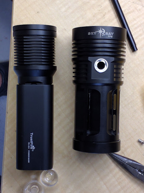
I had a left over head from the finger sizzler but decided it was too hard to make it work neatly.
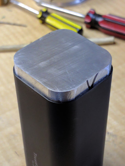
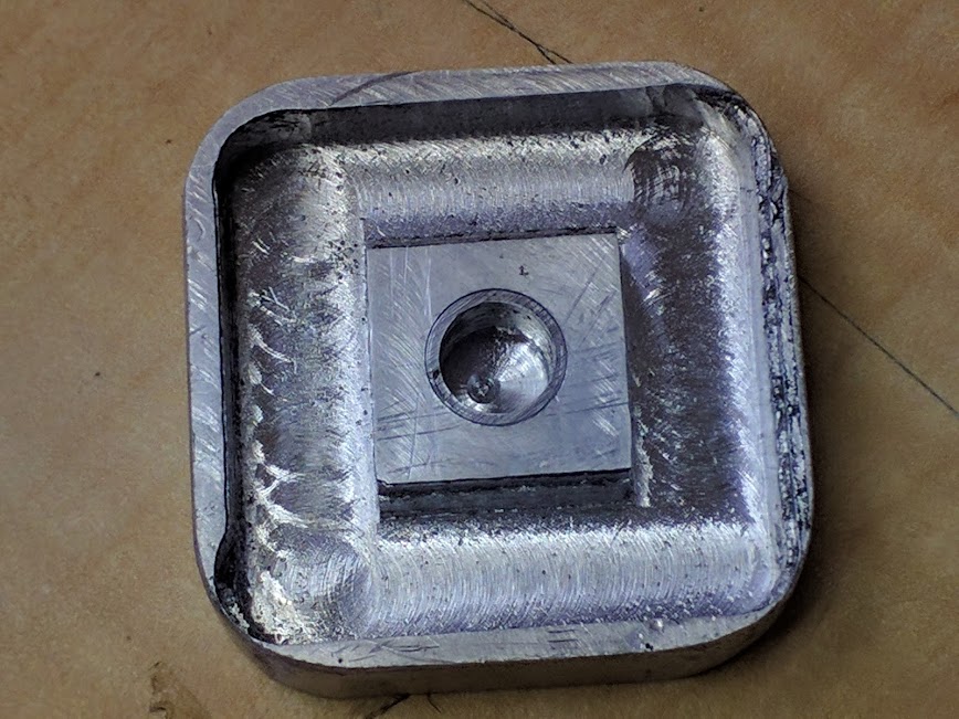
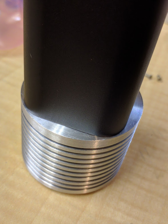
So I made a new head.
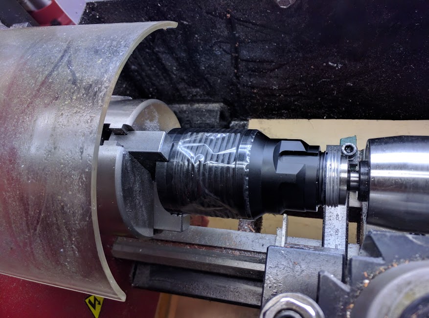
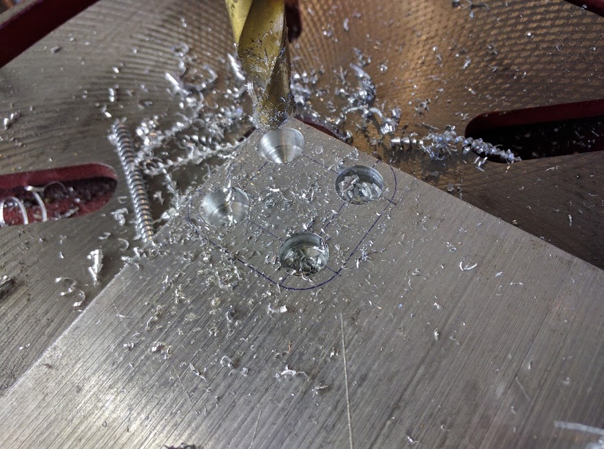
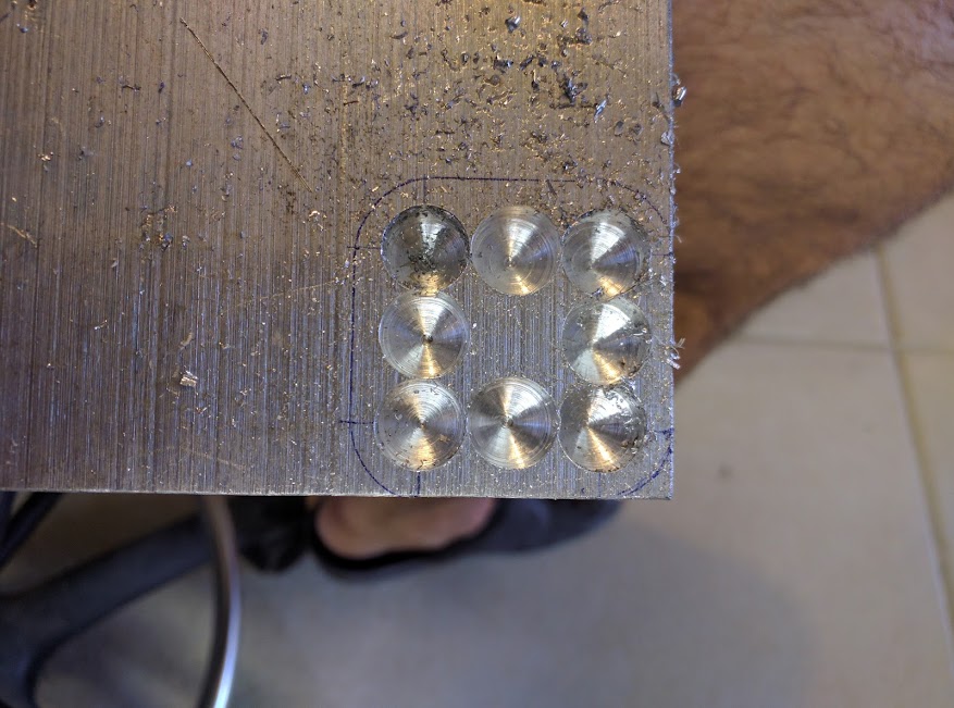
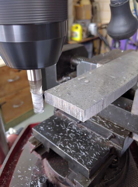
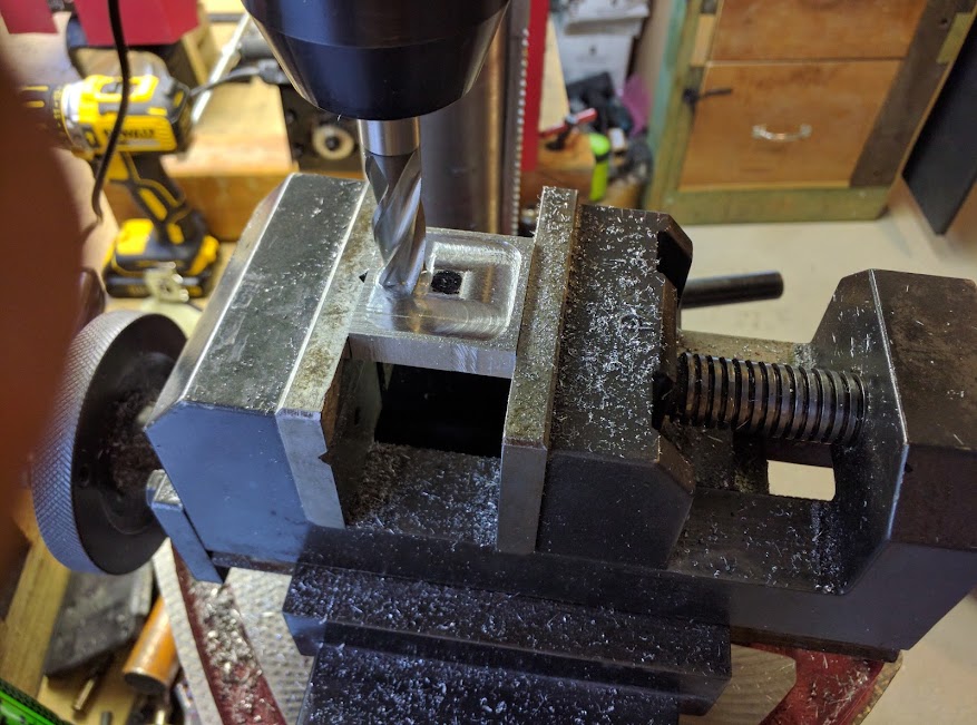
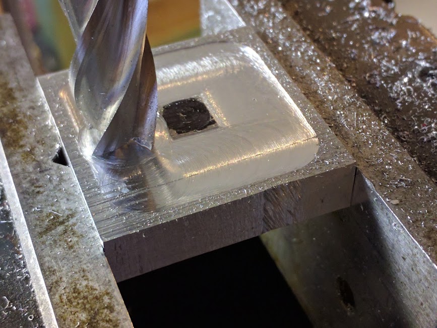
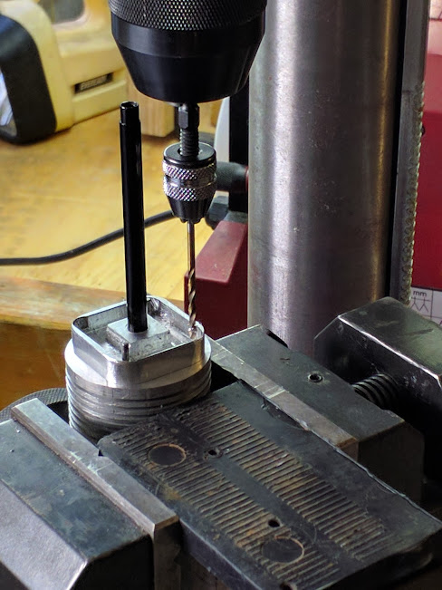
I wasn’t happy with this part so made it again. I pushed my cheapo drill press well past it’s abilities hence I made the part three times over.
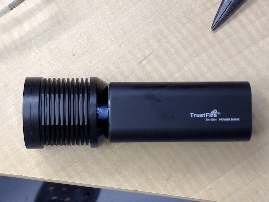
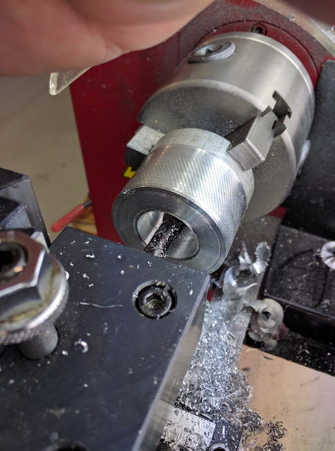
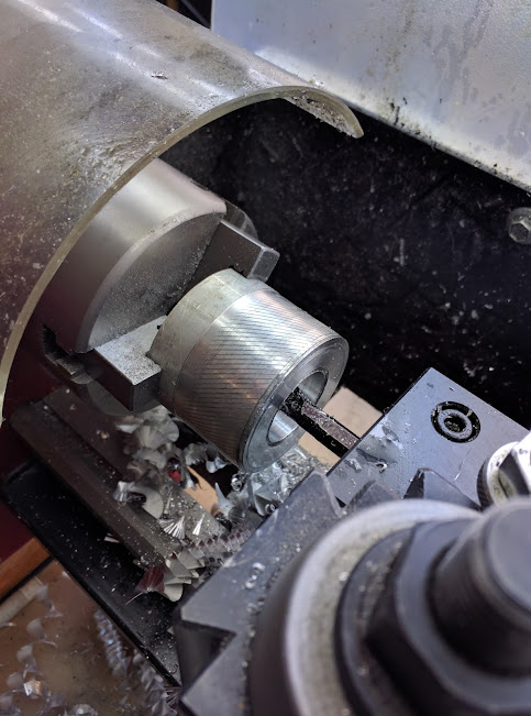
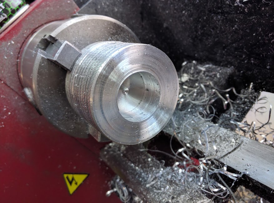
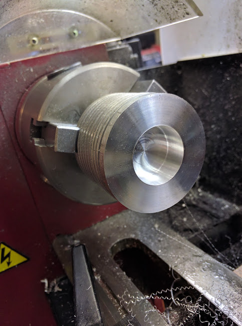
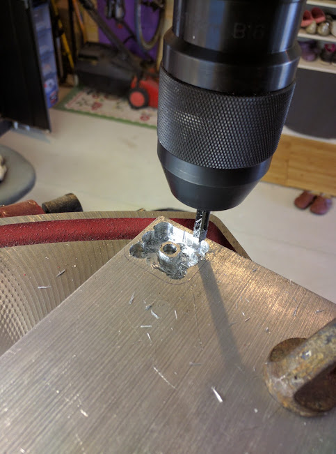
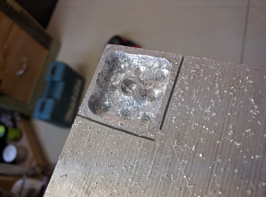
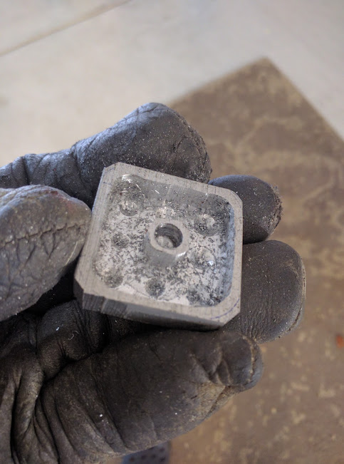
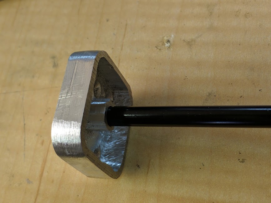
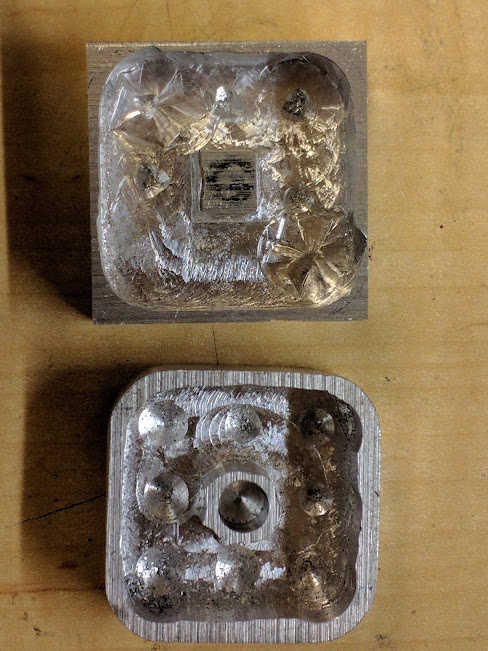
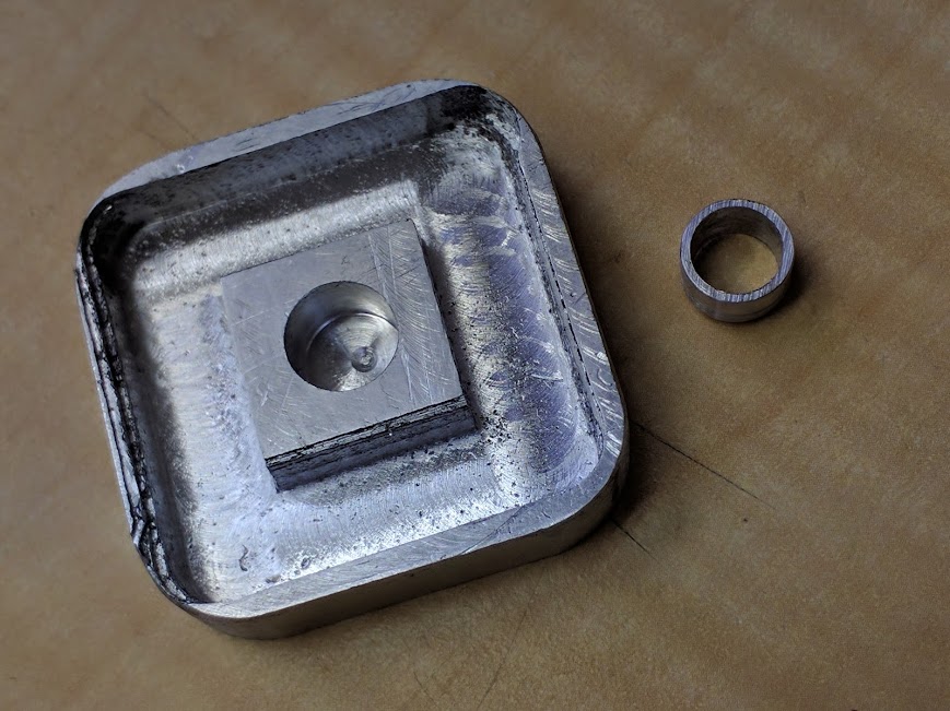
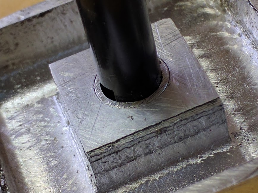
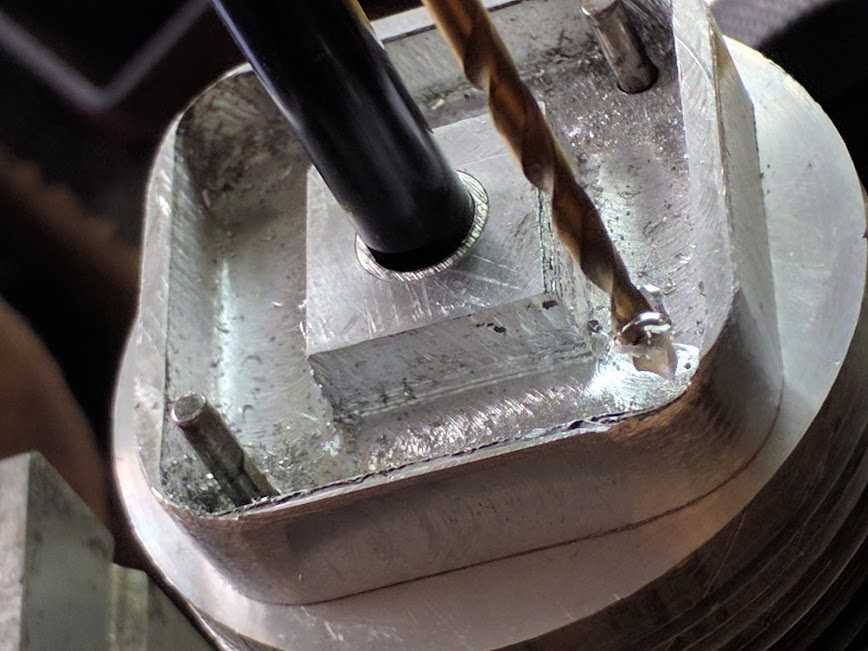
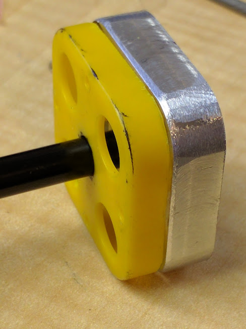
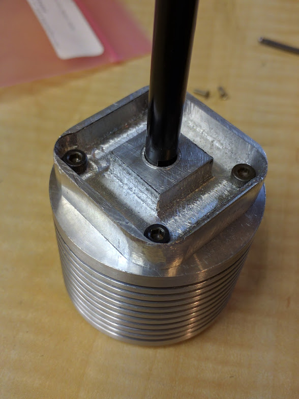
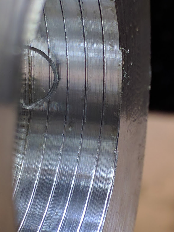
I was so pleased with the last one that I rushed into drilling the centre hole and …err… didn’t get it centre :person_facepalming: Rather than make it yet again I put it on the lathe (I have a 4 jaw chuck now) and reamed out the hole and inserted a sleeve.
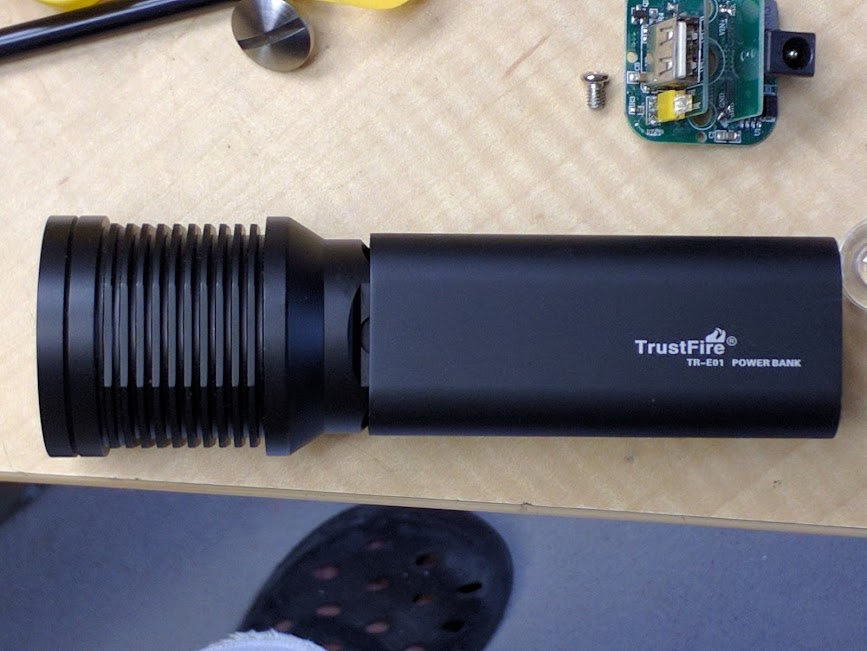
I just realized I haven’t taken a pic of it with the new head Still got lots to do with this…. To be continued
EDIT - 24-4-17
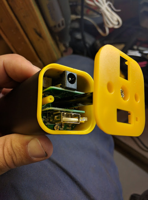
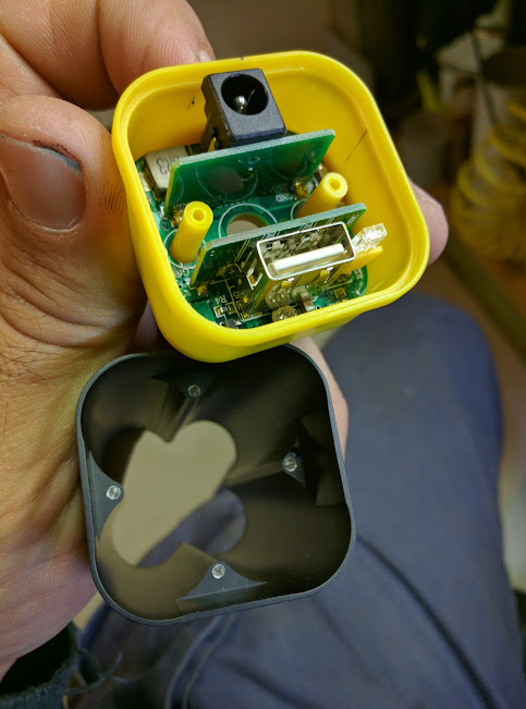
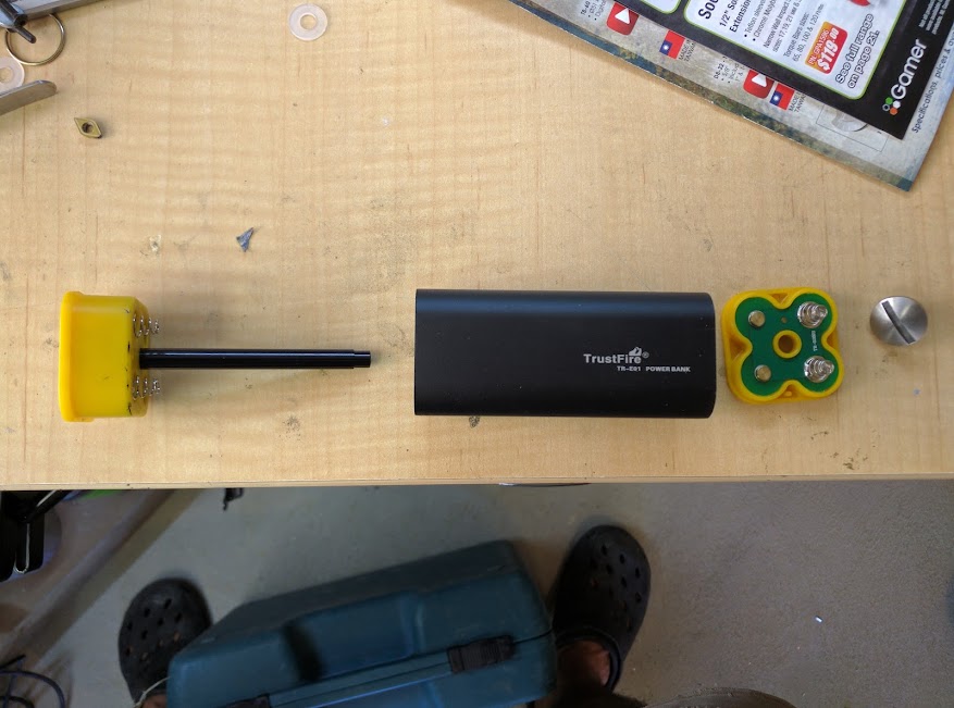
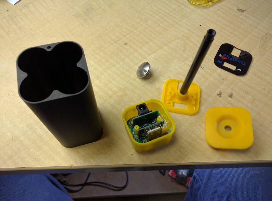
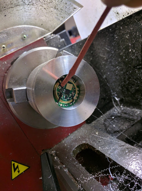
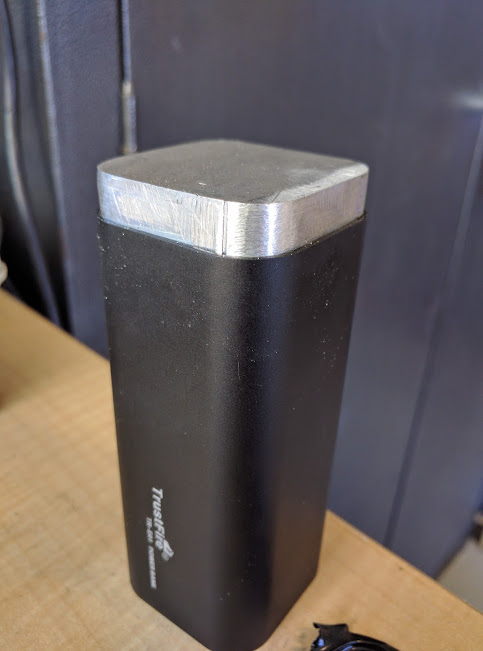
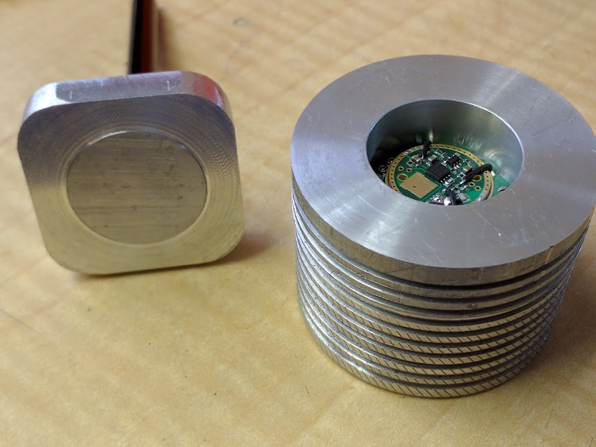
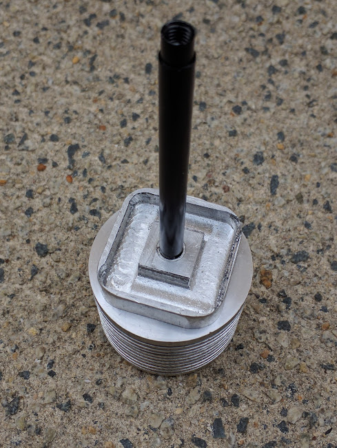
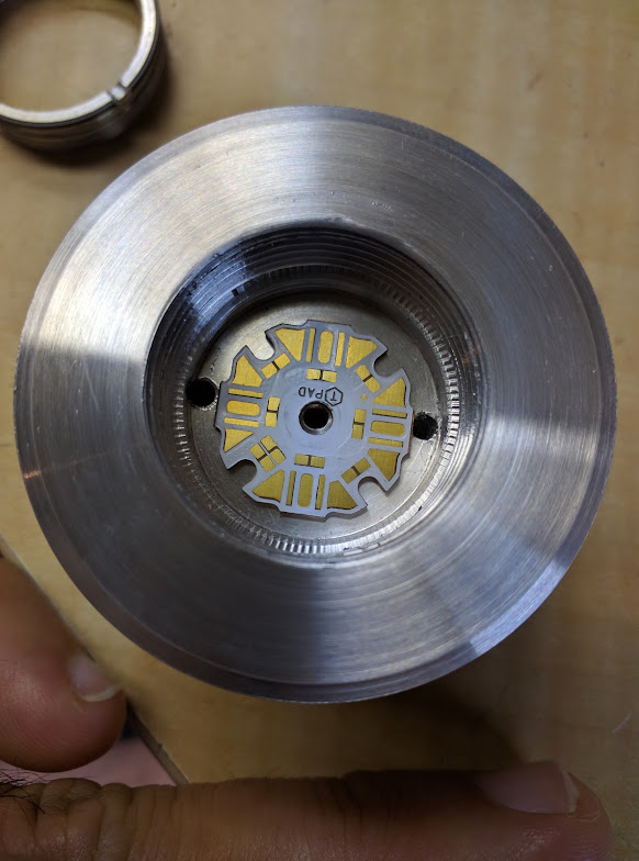
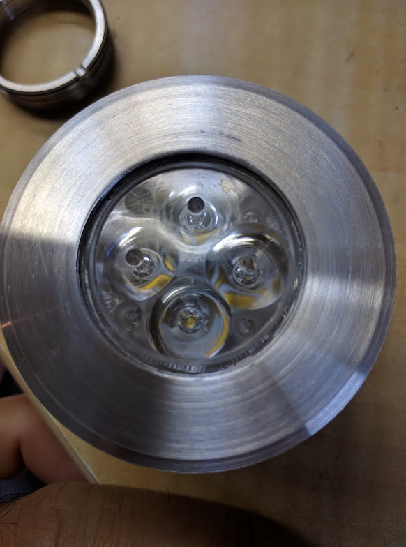
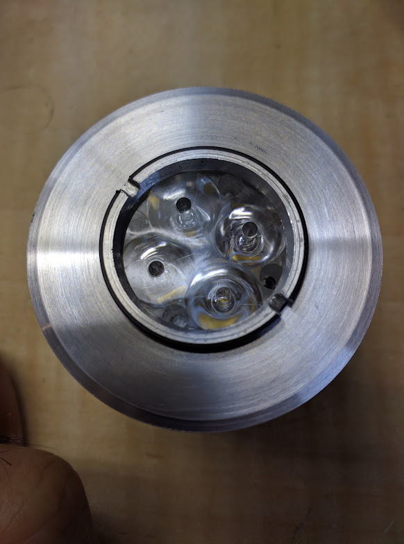
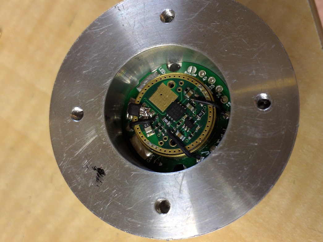
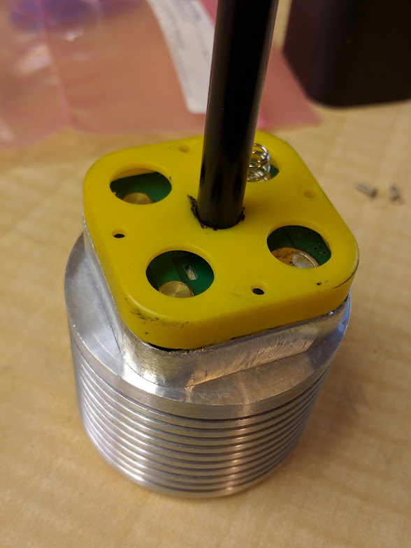
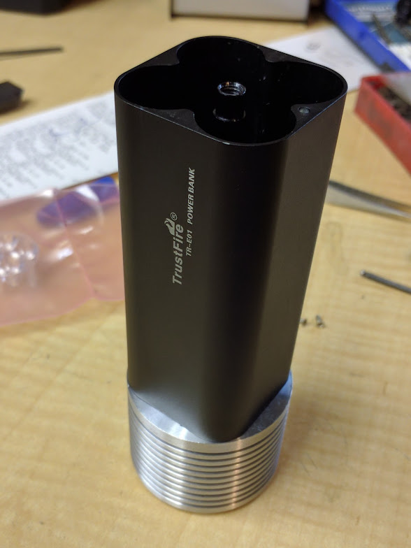
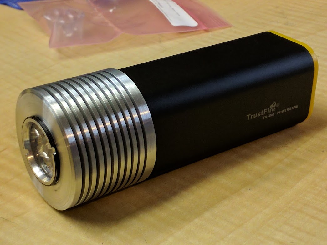
This morning I took some pics of assembly and the final look. Still need to work out a switch, reconfigure the cells from 2s2p to 4s and install all the components.
I’ve been having issues with threading on my lathe lately. I’m not sure but I suspect the plastic gears behind the head stock might be the reason.
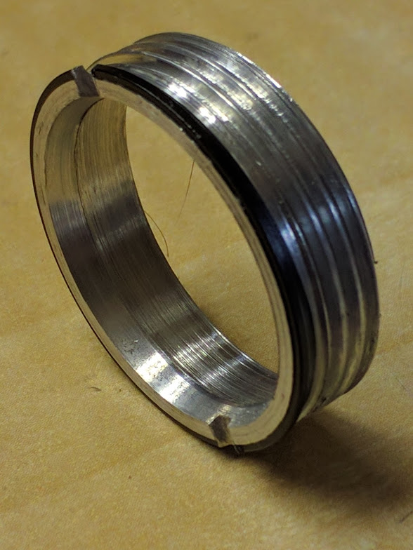
Have already posted this idea, but once again: this fins are useless without active (fan) cooling. For passive cooling you need at least 4mm between fins.
It would be interesting to compare the heat loss performance of this head to one with every other fin removed, to allow for better airflow. Less mass but better airflow… what would the outcome be?
Im into flashlight not so long, but before Ive seen lots of other powerfull devices. Look at cpu heatsinks. Before I got tons of special made heatsinks for passive cooled industrial lights, I have used usual intel heatsinks from lga775. Most of you know them for the solid copper center rod. They are useless without fan, cant handle even 10W power. All PC heatsink that made for work without fan have big distance between fins. Also, take a look at small heatsinks made for transistors and other parts in TO-220 or similar case. You can find them inside different devices, but without fan you wont find compact fins.
I too would be interested in seeing if anyone has done real life tests/experiments. Whilst I understand your theory isn’t walking around with light in hand somewhere between passive and active cooling? General assumption says the tips of the fins are coolest and that’s why shallow fins are more efficient (size, weight / heat emittance ratio). So any tests should be performed on a long finned item. That way the results should be more pronounced (greater difference between good and bad).
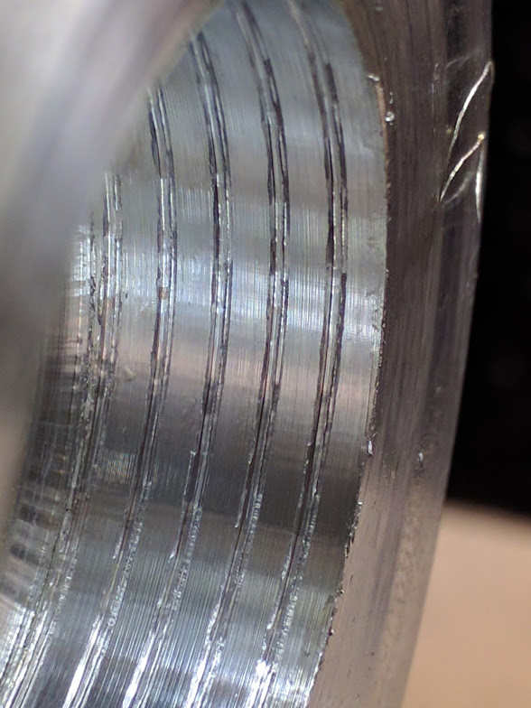
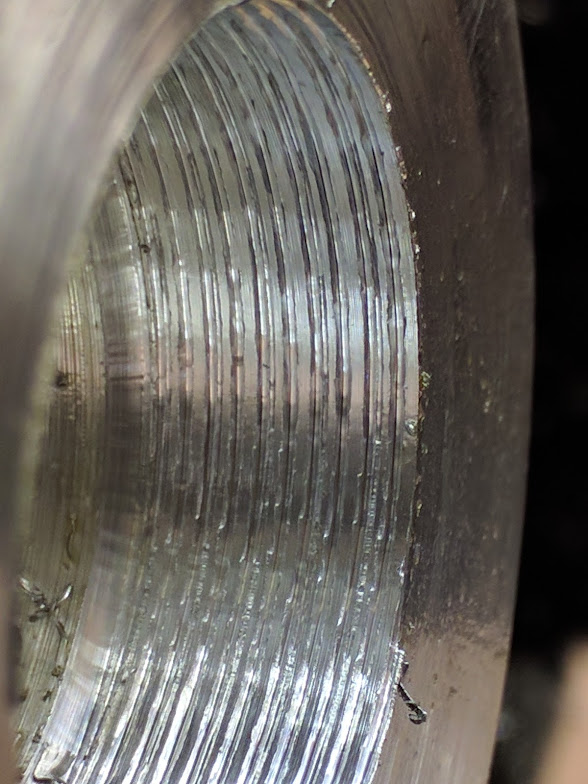
I was using an odd set up for threading. I had an external threading tool mounted internally on the back side with the lathe in reverse. The carbide bit is designed to cut in that direction. If that doesn’t make sense basically I had it rigged so I was threading out of the head instead of into it.
Because I was having issue I tried to cut under power using the thread dial, engaging/disengaging at #1 only. I tried under power leaving the half nut engaged and reversing the lathe. Also I tried turning the chuck by hand with the half nut engaged and reversing.
All three ways seemed similarly as inaccurate. So that’s why I think it might be in the drive train. Though I when I look into it I will check if there is any slop in the half nut.
I googled air cooling fin spacing and found lots of technical info, too technical for me right now. However, there were a couple of examples of how cooling was increased by keeping the overall heat sink dimensions (L x W x H) the same but reducing the fin count in half by increasing the spacing. One example went from a heat sink that failed to one that worked by cutting the count like that. Plus the heat sink cost less as there was less material used.