Keep in mind that the battery is not at 3.5V when it trips at 5A. The voltage @ 5A is 3v (or whatever the step down point is set to), which leaves a mere ~150ma charge remaining, or about 5%.
Notice in those HJK plots that the tests that he stopped early, the voltage recovers a lot when the load is cut, you are seeing the same thing in the light. Don’t confuse the reading you get after the load is cut with the voltage the cell was at under load. The under load voltage is what matters when comparing it to the plot.
‘Hi-drain’ cells should actually do better than low quality (or regular cells) at the same current: Lower internal resistance, lower voltage drop.
As TA said (and I tried to say in #143), I think the HKJ voltages are measured under load. So on the 5 A curve, when the cell shows 3.5 V, it is while under 5 A load. And if you then remove the load and measure the voltage again, it is going to be around 3.7 V for 30Qs.
Well, my point why hi drain cells would do worse is the amps will be higher when it reaches the trip point (whether 3.0V, 3.2V, 3.4V, etc.), so the voltage drop is greater because of the higher amps.
Ok, I see it now, comparing a 0.2A curve against a 5A curve on the 30Q.
To optimize battery usage, you really want to be close or below the point voltage starts dropping at a higher rate (curve dips down). 3.2V to 3.4V or below looks good for the 30Q and SANYO GA cells. Interesting the 26650 cells in general have a much steeper drop off.
I think you are overthinking it. Pick a good step down point and run with it. I agree with DEL, Personally I am a fan of a ~3.3v step down with a ~2.8V cutoff. This way I get a good runtime during the stepdown process and I still have a worthwhile amount of runtime left in moon mode should I need it.
You could even allow for a low ~10-15 lumen mode after the final step down instead of moon mode only. 10-15 lumens is enough for most things and yet would still give you several hours of runtime even at those low voltages. Then have it step down to moon mode only once voltage drops below 2.9v.
DEL - any thoughts on building a LDO version of your Y3 driver? Came up in this thread: https://budgetlightforum.com/t/-/45440. someone else look'n to do the same thing I'd like to do - XHP50.2 in a Y3. I got the extra Y3 extenders.
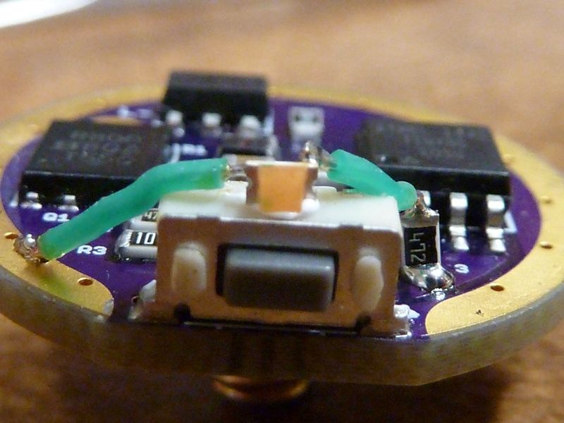
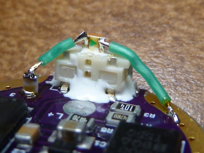
Wait, photobucket and Chrome are not cooperating, once again. Wanted to check my pics. Think I mounted the LED on top of the switch. For these somewhat transparent switch covers, you have to maximize the position of the LED to keep it's power draw relatively low. If it were to lay flat on the driver, it's not an efficient setup.
Ok, here it is:
Electronic art That's 30 AWG stranded wire. Got it in a few colors, comes in very handy.
This seems the best way for a Y3, though might be a pain for some working this way.
The resistor value of 4.7K is relatively low because it's a yellow LED, I believe, in this case. Colors like green are pretty bright, so a higher resistor value can work well. In the BLF Q8, I'm using a 15K resistor - still pretty bright even but nice low power draw. The Q8 has two green LED's mounted directly on the switch PCB - best setup, and maybe helped by a more translucent switch cover, and I thnk maybe pretty bright green LED's they are using.
Yes, don’t see a way to point a board-mounted LED to the switch boot, even if side-edge mounted. Top-center of the switch like you did will be optimal.
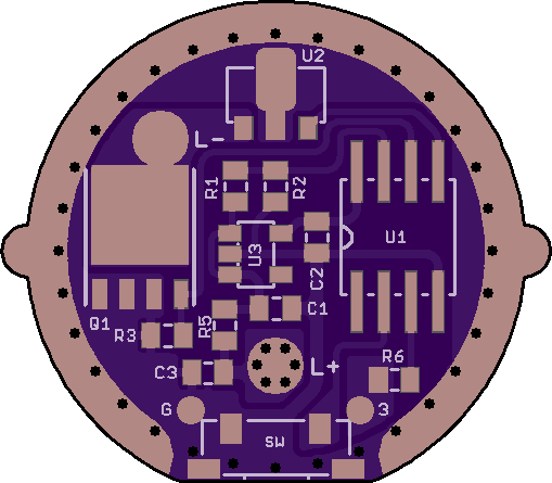
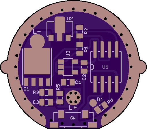
Should then just try to have two convenient pads around the switch to wire to. Can flip R6 and the D1 pad around and add a mirrored ground pad west of the switch.
OK, cleaned it up a little and added pads to air-wire an indicator LED. The share is up:
C2 is the only critical capacitor. It needs to be at least 2.2 uF and good quality. 4.7 uF is a good number for all three to keep it simple. The ‘standard’ 10 uF is a little excessive, but will also work. All pad sizes are 0603, but they are generous and 0805 parts will fit.
C3 is experimental. It should suppress the inductive ringing that finds its way back to the cells when the FET is PWMed. Hopefully it will prevent the 7135 deaths that Tom and TA experienced with 2S DD+1 lights.
LDO regulator is the MIC5235-5 in SOT23-5 package. Pin 1 in, Pin 5 out. Others may work, but the MIC5235 has low parasitic drain, reverse polarity protection and reverse leakage protection. The board can be used for 1S without the LDO, just place a Schottky across LDO pads 1-5.
Nice work DEL! I see on the OSHPark listing you are suggesting 10 ohm for R5 instead of 4.7, and the 47 ohm R4 has been eliminated. I assume the R3 is still 100K, I believe?
Pretty sure I got quality 4.7 caps, so good there. I believe those are the LDO's I have, bought here:
With a 2S light we have the luxury of MCU feed voltage to burn, so R5 can go larger. Larger helps the R5/C1 filtering. But whatever you have in 1-22 ohm is workable.
R3 can be 22k to 100k, as usual. Larger is more benign. I always use 100k and never had the inadvertent flash phenomena.
R4 is a nice-to-have, was a little too crowded to fit it and have nice routing.
The MIC is still $1.20 in singles at Digikey. And the price break is only at 25 units. Should try Arrow someday.
K, then. Should be ok for me to place the order now? Just want to be sure you are ok with the design, or want any more time. Are you ordering them?
Dang, you got me think'n bout this issue addressing with C3... Got a Maxtoch Mission M12 want to use a XHP50.2 in, plus couple other 2S lights with a XHP70 or XHP50/XHP50.2.
It should be ready to order. Mechanically it is identical to the 1S version. Electrically it is not tested of course. I do not have a use for it, unfortunately. Only two Y3s and both with single-cell tube only.
The C3 add-on should be easy to test on any driver. It simply sits over bat+ to bat-. Can even tack it on between the spring and the ground ring.
Subscribing. I know I’ve been MIA for a long, long while… But both of my modded Y3’s drivers are halfway dead (one running an xml2, one running an mtg2). Starting to miss having them operational, so I reckon I may be getting some of these to build.
Welcome Back! Wondering what your driver problems are. I've seen the switch get bent back on one heavily used Y3 - had to fix it up. With DEL's driver we can use a better quality switch, plus beef it up to have more rigid support.
Apologize in advance for the thread-jack… With both the first issue to pop up was the low voltage step down started kicking in earlier and earlier. The mtg2 would start flashing after less than 5 min on fully-charged batteries. Then it quit driving full power to the LED and now operates on probably 1/4 of normal power levels on all modes, regardless of battery voltage. I haven’t measured it to see exactly what it’s outputting to the LED. The Y3 I have with an xml2 does the same thing, but it started after it got dropped one time. It also did the LVP drop prematurely as well. Both drivers are resistor modded. Can’t remember what values off the top of my head.


 That's 30 AWG stranded wire. Got it in a few colors, comes in very handy.