Test/review of Charger 1.5A 3.6-4.2V (TP5000)

Charger 1.5A 3.6-4.2V (TP5000)


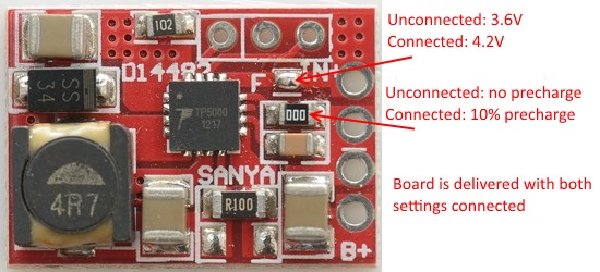
This is a charger module from ebay, it is based on the TP5000 charge controller, depending on settings it can either charge with 4.2 volt or 3.6 volt.

The official specifications from the ebay page is:

  • PCB size:21.5*14.5*4.2mm

  • Input voltage: DC 4.5-9V(Recommended not to exceed 7V)

  • Output voltage: DC 4.2V/3.6V(default 4.2V)

  • Output current: 1A(Default max)

  • LED Indicator: Charging-Red/Green Flashing,Charged-Green

  • Features: Charging for Lithium battery(4.2V) and Lithium iron phosphate battery(3.6V)


I got it from ebay dealer: e_zealot


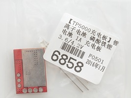
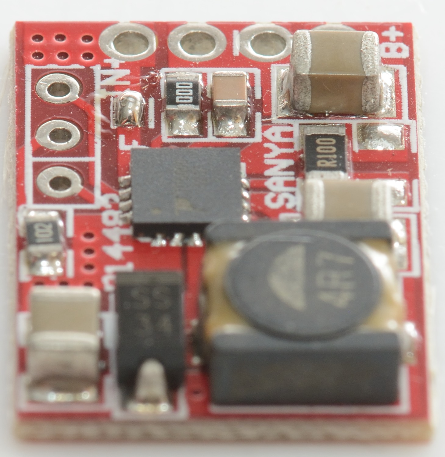
I got it in this bag without the led soldered in.


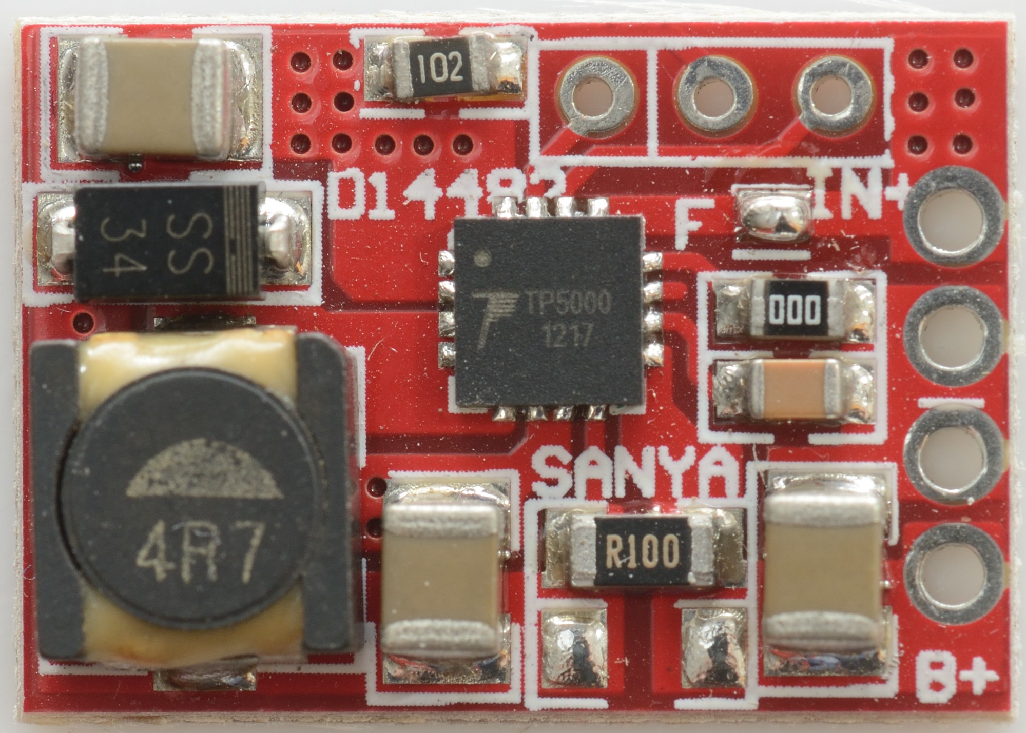
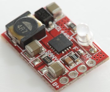
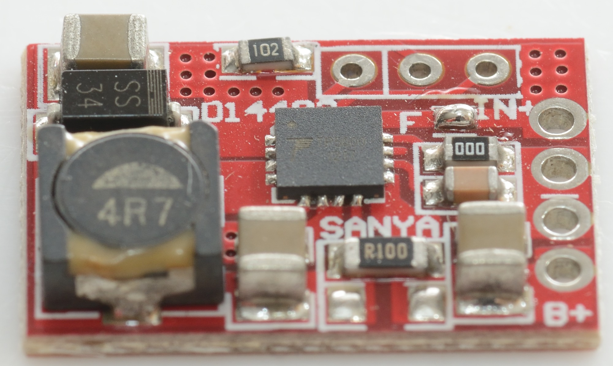
There is only components on one side of the circuit board. The charger is one switcher chip with inductor, diode and current sense resistor(s).


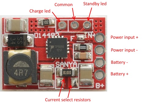
The supplied led is a 3 pin two color led that fits directly in the holes.


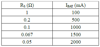
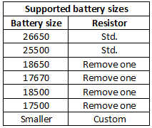
The charge current can be anything from 0.1A to 2A, this table shows some of the possibilities. Without a heatsink it is best to keep the current at 1A or lower.


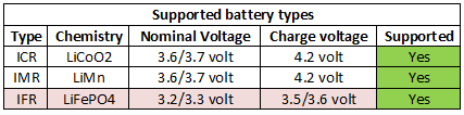
Charging LiFePO4 works, but is not ideal.


Measurements
  • Power consumption when idle is 0.1 watt

  • Discharge with 3uA when not connected to power.

  • Discharge with 8uA when connected to power (5 volt supply).

  • Will restart if battery voltage drops to 4 volt (4.2V setting).

  • Will restart if battery voltage drops to 3.45 volt (3.6V setting).

  • From 0 to 1 volt it will charge with 0.4A (1A setting).

  • From 1 to 2.9 volt it will charge with 0.1A (4.2V/1A setting).

  • From 1 to 2.4 volt it will charge with 0.1A (3.6V/1A setting).


Charging 4.2V LiIon


This looks like a good CC/CV charging with termination a bit below 10% of charge current.
Compared to linear regulators this regulator reduces current closer to 4.2V, this will make the charging a bit faster.


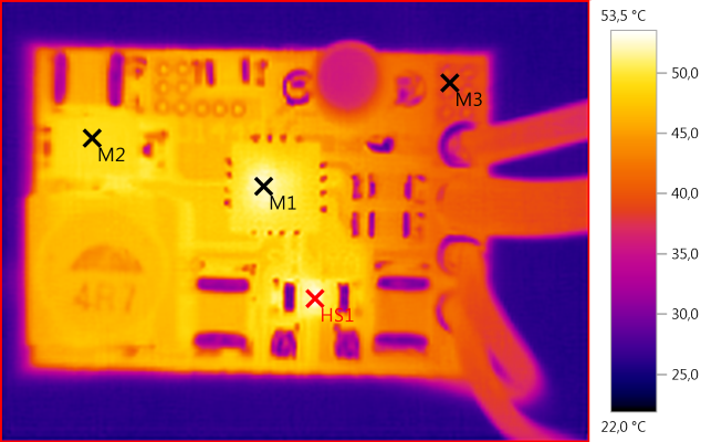
M1: 52,3°C, M2: 49,2°C, M3: 39,3°C, HS1: 53,5°C
Everything on the circuit board stays fairly cool at 1A


With 9V input the charge reduces the current slightly.


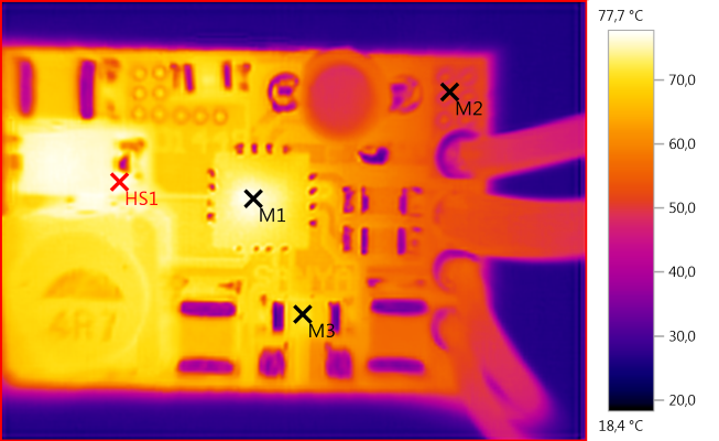
M1: 77,0°C, M2: 50,3°C, M3: 71,2°C, HS1: 77,7°C
With the higher input voltage everything gets a bit warmer.


The other capacities are charged fine.


The old cell goes into CV phase fairly early (As expected).


Changing the current sense resistor to 0.22ohm reduces the current ot about 0.45A, the termination current will also be reduced.


A 0.5ohm current sense resistor means 0.2A charge current.


Adding a 0.5ohm resistor in series with the power supply do not affect the charging.


With a 5ohm resistor the charging is slowed down, but still works correctly.


Charging 3.6V LiIon


Breaking the 3.6 volt jumper I tried charging a LiFePO4 cell. The charge voltage is fine, but I do not like the automatic restart, it is placed at too high voltage.


Conclusion

It is a nice module for charging 4.2 volt LiIon batteries, even fairly small ones, the flexibility in input voltage makes it useful for 6V unregulated solar panels.

For charging at more than 1A it is best to mount it on a small metal plate with electric isolation between.


Notes

This is the second TP5000 module I have reviewed, the first is here.

Here is an explanation on how I did the above charge curves: How do I test a charger

Used a couple of the TP5000 charger boards, I prefer them to the TP4056 now.

Thanks for the review :+1:

Thanks HKJ. Interesting review. :+1:

Not bad, in line with the older TP5000 board review.

The problem with this stuff is that there are plenty of good and inexpensive offers for DC-DC CC/CV XL4005/XL4015 modules, and these are more flexible with fully configurable output voltage and current:

1/2/5/10Pcs Lithium Charger 5A CV Buck Step Down Power Supply Module LED Driver @ cayin35 - eBay - Waiting for one of these.

Also got one (a couple) of these, but from other sellers: Lithium Battery Charging Board LED Constant Current/Voltage Drive Power 5A Module @ erizh-51 - eBay

I like to tune down li-ion charging voltage to improve cell life cycle.

I'd love to see those HKJ reviewed. The russians seem to like them.

Cheers ^:)

I have reviewed a few power modules, but they are not charges, this means they do never terminate.

The aforementioned modules are configured to terminate at 10% of the CC trimpot set value, there are leds to point this out onboard. I have one unused lying around, maybe I should check this.

I also have a question in this regard: if these modules do actually feature a 10% set current cutoff, does this mean we could arrange these in parallel safely without having to worry about inter-module current “cross-flow”? Well, since the output voltage can be precisely fine tuned, I believe this should work. Of course, if in doubt a handful of high current schottkies is all this would need, but this can be a little problematic with fine-tuning the output voltage due to the current dependent drop in the diodes.

Cheers ^:)

My impression was that the low current setting only turned on a led and did not do anything else (like terminating charge).

Good. I see no reason to actually terminate, and this means the cells can get full-filled. :THUMBS-UP:

If this is so, my guess is high current diodes in series would be needed to set modules in parallel without magical smoke issues. However, I wonder how much current crossflow could appear fine tuning Vout within ≈1mV.

Thanks for the input.

If using a new Soshine 18650 LiFePO4 cell should I leave the 10% precharge connection unchanged or should I de-solder it?

DoubleA, leave the precharge connection unchanged, it is meant for gentle charging of over-discharged cells. Reason to disable it is if using these TP5000 modules as led drivers (HKJ mentioned this here).

Cheers

Yes I understood that part, it’s about recovering over-discharged cells, but I was talking about new cells, probably with some protection circuitry built in. Should I still leave the connection unchanged? :frowning:

Let's make it easy, DoubleA:

¿Do you plan on using this module as battery charger? Leave the precharging setting as it is.

¿Do you plan on using it as a led driver? Remove it. If not, you won't get the full driving current for low Vf leds (below minimum cell voltage thresholds).

Cheers :-)

P.S.: as a gross barbarian I am, I'd probably remove the jumper anyway. :-D

Ok I got that… Thanks, I’ll leave the connection as it is for now.

Now just have to decide which one of these TP5000 modules to buy since aliexpress shows a handful of different variants.

About that current select resistor part, should I add a new resistor in the empty slot or should I just replace the existing resistor to a different value? I wanted to charge 14500 cells at 300mA current so please help me out here.

The two resistors are in parallel, adding a resistor will increase the current, you want less current. That means you have to remove the existing resistor.

Ok, so the existing SMD resistor R100 (0.1Ω) will give 1A charge current, and if replaced with a 1Ω resistor then the charge current decreases to 100mA right. But this is where it’s confusing to me, according to your table why does 0.2Ω give 500mA Current? shouldn’t that be 0.5Ω?

The data sheet for TP5000 says the formula is: Rs=0.1V/Ibat (Rs in ohm, Ibat in Amps)

Thanks for the formula. Guess I will remove the existing resistor and add three 1Ω resistors in parallel to get 0.33Ω so with that formula this resistance should give 300mA of charge current. :+1:

Do not expect the formula to be exact, there is some component tolerances.

I’ll check the current output with my multimeter before I implement it. :slight_smile: