Hello friends, I have a problem with my L2, I have it mounted with XP-G2 S4 2B and in direct drive and only managed to get 2.70 A (tail). Eh disassembled everything and tested the carried from a dissipating base (photo) and just arrived at 2.75A. Also tested with another XP-G2 dedomed and the same, some imagines what is my problem ?? The batteries are 30Q and a full charge is charged
Did you use this same set-up to test the amp draw when this emitter was in your L2, if so try shortening your leads! To about 3-4 inches, see if your draw go’s up?
Thanks, that’s right, I used the same system, I shortened the cables to 5 cm and I still with 2.75 / 2.80 amps, the same with the other XP-G2, this problem does not let me sleep …
Your never going to get a decent reading with that setup. Some multi-meters get close, some never do. If you really want to know the amp draw you’ll need a clamp meter.
Another good and inexpensive way to accurately measure current is to use a shunt. It is basically a piece of wire with a known resistance. You complete the circuit with the shunt and measure the voltage across the wire and calculate the current. The one I use has about 10 mOhms resistance, which works well for me because this is a typical resistance of a tail switch with bypassed spring. You do have to accurately measure the resistance of the shunt, but this can be done pretty easily if you have 2 DMMs, one to measure the current through the shunt and one to measure the voltage across it.
I just put a de-domed XP-G2 in a Jaxman X1 and built a 22mm Mtn FET driver for it, with bypassed springs and a clamp meter and using an Efest 3500mAh cell I only get 3.51A at the tail. I’m thinking the emitter has a very high Vf…
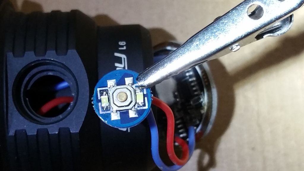
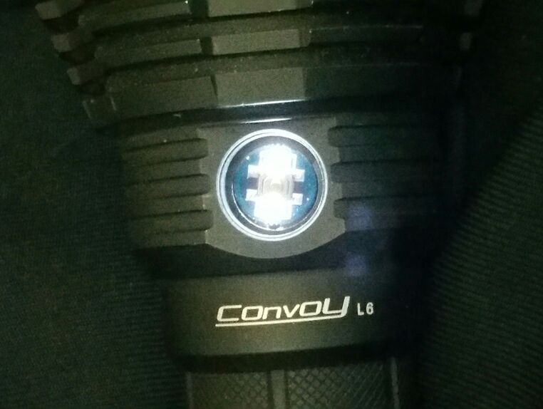
I just finished my lighted side switch. A complete success on the first try!
This light has the FX30 driver from Kaidomain with the weird firmware that let’s you turn the light on and off with the side switch. The only problem is telling if the rear switch is on or off. I’m always double checking it. Now I always know plus can find the switch in the dark. No more fumbling for it! Yay!
First I filed out some notches to the switch hole to allow easier driver swaps. Kudos to Kawiboy for the suggestion.
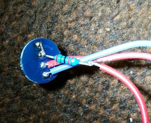
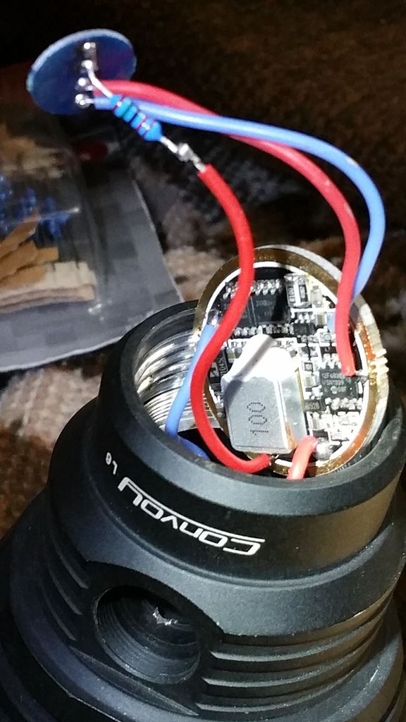
Then I took 2 white SMD LEDS, kudos to DBCUSTOM for the LEDs, and added them like in my diagram above.
I bridged the rear connector to get power to both LEDs. The resistor is a 15K ohm. I believe that’s equivalent to 7.5k ohm per LED. It’s bright enough, but not too bright. The amp draw went from 1.45 milliamp to 1.85 milliamp. So no big deal for me.
JasonWW thank you for sharing the above, wish I had known about the little notches in the side switch mounting hole trick (Kawiboy). Will do that on the next one.