I looked at doing this lighted switch design on my Black L6, but it’s got an FET driver and I wasn’t sure where to draw power… figured the switch wire was coming from the MCU which had a regulated voltage of >5.5V due to the Zener mod, but couldn’t get it to work… might have something to do with my pain meds, don’t know. ![]() I have LED’s on the board, will look into it later.
I have LED’s on the board, will look into it later.
If you run an inline resistor you can run the switch LED’s off the full voltage no problem.
I took the driver out and used magnets to hold the batteries together and to hold the negative wire to the battery. Then I pressed the driver spring up against the battery positive. It was pretty tricky to do. Then I could use my multimeter to find a constant source of positive power on the top of the driver.
He’s gotta find full voltage first. He’s got a zener modded MTN17DD driver.
For the full voltage simply connect to the V+ from the main LED and then to ground via a resistor. Lots of grounds you can use from the input to the FET or the ground ring, OTC ground, C1 ground ect.
Built hundreds of FET drivers, pretty much know the drill there. Just not used to using these tiny SMD LED’s. Nor am I used to doing the mods so heavily drugged. :confounded: Probably shouldn’t, have burned myself a few times lately. Left hand and arm are totally out of whack.
Jason, the package those LED’s came in identifies them as SMD SMT 080. Hope that helps. I got 8 colors, 20 in each tape, for like $8 and some change on ebay.
they are most likely 0805 LED’s. These are cheap and easy to get on ebay. You can get 100 of them for like $2.
I have hundreds laying around for building lighted tailcaps.
That would only light the side switch when the main beam is on (and not needed then), but not when the light is in standby mode.
My whole reason for wanting the lighted side switch is so I would know whether the rear tail switch is on or off. It also helps to locate the switch in the dark instead of having to feel for it.
By connecting the side switch LED to the main led V+ and then to the ground ring via a resistor (most likely between 25-50k), the LED will be on anytime power is applied to the driver. The V+ is connected directly to the battery and so in the ground ring.
Okay, so there is always battery positive going to the emitter and it’s the negative wire from the emitter that the driver controls/manipulates?
Is that how all drivers work or do some control the positive wire going to the emitter?
I’m still not sure how power flows through a driver.
In all the FET based drivers we use the positive is always connected, we only control the ground. Since you are bypassing the 7135/FET by going directly to the ground ring (with any of the connection points I listed above) the LED always gets power when power is applied to the driver.
You would need a firmware and driver that supports an indicator LED in order to control the LED past that.
I could have done this instead of searching and probing for a positive battery source? I didn’t bother to check this because I assumed it only had power when the main beam was turned on.

Well what I said above applies to the BLF FET drivers in reply to DB. Some buck and boost drivers do switch the positive side, so you need to see if yours is one of those. If so then you can usually tie into the LED ground and then into a voltage source.
The easiest way to find the V+ voltage source is generally to look for the vias from the spring and see where they come up and follow them to the first easy to tap into location.
Okay, so it’s best to take it case by case. Don’t assume. Just apply power to the driver and probe around to make sure you find a good voltage source.
My next driver is going to be one of yours and it has a spot to add a “power on” led. Now since the led has to use the same negative wire as the momentary switch, can you tell me which pad is positive and negative?
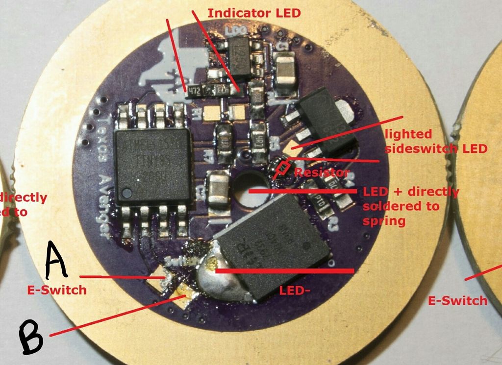
I labeled them A and B.
Hmmm, maybe it’s not important. I can try the red switch wire to A and the blue switch wire to B. If the LED doesn’t light, I can switch them around.
Nope, that could damage the driver. Pad A is for the red switch wire and pad B is the ground so that gets the blue switch wire.
Oops, forgot the picture.
If you are using narsil with the indicator LED then it needs to go to the correct pin, no idea which one that is as I have never used it.
If just having it on anytime power is applied then it would work the same as I listed above, you could use the bleeder resistor pads as well.
I’ll have Narsil v1.2.
I’m not using the “indicator” led. I’m not sure what it’s supposed to be used for actually, but I just need a simple light to tell me if the rear switch is on or off. Nothing fancy. Positive power to the switch LED is shown on the picture above (lighted side switch). I’ll use a smd resistor to drop the power down.
The negative side of the switch LED shares the same wire as the momentary switch. So polarity of the momentary switch is a factor.
You can connect the negative wire to any of the locations I listed above, they all go to the same place, the ground ring. Indeed the e-switch ground is perfectly fine.
The positive is the only thing you need to worry about, in the case of the TA driver the easiest V+ is the bleeder resistor, the pad closest to the LED V+ wire.
I think I have it figured out now.
I can see a lot of new folks with the TA driver in an L6 that might want to do a simple lighted side switch. ![]()
Well, I tried it and failed… again. I tried to use a 22K resistor but that’s not going to work, not without some form of support, as the end cap simply pulls off the resistor. In trying this, I somehow messed up my FET driver. Ended up removing the SIR800DP FET and replacing it with an SIR404DP. I have it working again, without the lighted switch but with a clear boot cover and led’s on board. Still have to figure out how to power em up.
I now am getting 12.03A at the tail with the Uni-T clamp meter and 7077.5 lumens with these LiitoKala 5000mAh cells.
These pain meds are totally screwing me up! Even the MCU ended up coming off the driver! Heating up the board with my hot air to remove the FET I somehow got the MCU loose and ended up with it literally falling off when I was trying to test everything. One thing after another when you’re mentally least ready to deal with it all, but of course.