Yes, amd welcome to BLF!
You are full of surprises Tom. Yes this works perfectly as Miller has mentioned. :+1:
Funny how a bug becomes a "feature" 
I was gonna stomp this one out, but it just seemed too handy.
During this whole thread I don’t think there’s been a single picture of the switch pcb.
Does anyone have a picture of the swicth from the light or of the same model switch?
I’m curious if there are pads to run 2 leds. If so, we could customize the switch colors. Either 2 of the same color for a more consistent look or blue and red for a purplish color, etc…
As long as we double the existing led resistance, the led drain should only double to 270 µA. Totally worth it in my opinion for a customized look.
Anyone putting the light up on a shelf and not using it just needs to do the 4 clicks to lockout the switch and boom, no more led drain. It can sit for years.
MARK
Aha, just typed
1337 dhsvcs 3rd
and a thought flashed through my mind: “hmm 1337 is a funny number, shall I propose to close the list now so this is the latest entry?”
![]()
nah we have also passed that, next chance would be 1357 ![]()
heheh nice, aren’t all bugs features or features bugs, confused ![]()
Yes here you go!

And I only have pliers that require force to close them, the switch cover needs them to be pushed outwards, so time to make the round metal part around the translucent switch metal colow ![]()
I really should explain this more. Why this quick click works to turn off the switch LED is because the switch LED flashes 1 or 2 times, depending whether it's in the 7135 (channel 1) zone or the FET (channel 2 zone). But when you click the switch during the blinking, it bails out of blinking leaving the switch LED in a state of OFF. It was unintended to happen this way, so was gonna add little code to fix it, but glad I didn't.
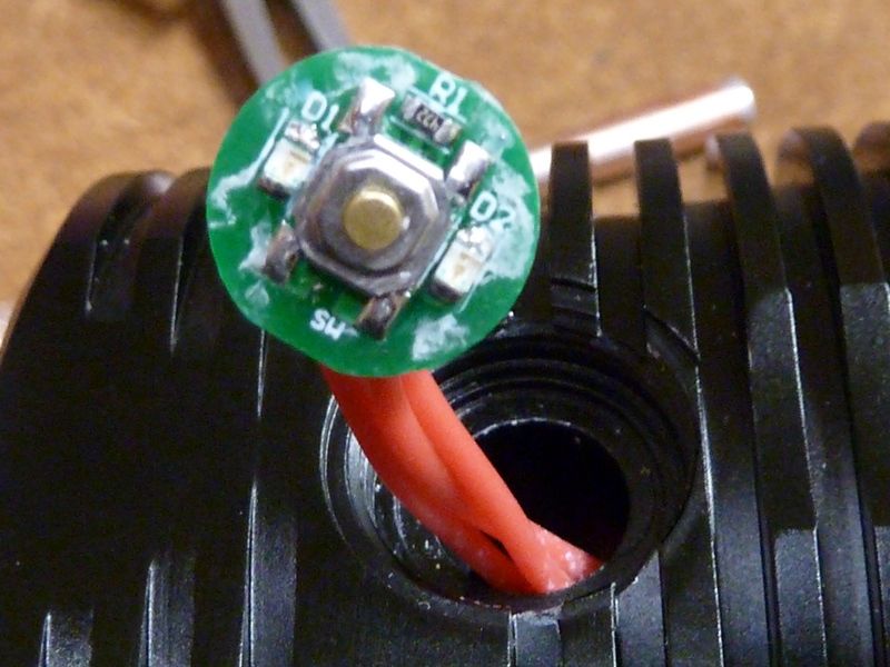
Here's the pic of the switch PCB. This is from the round 2 prototype but the round 3 version should be the same, accept for the resistor - we had them change it from 4.7K to 15K because it was just way too bright, and therefor the parasitic drain was higher with it on. It's not a great pic, maybe I didn't post it because of that, dunno. But you can clearly see the two LED's on the side and resistor on top. The resistor connects to both LED's, so they are in parallel - can't be individually addressed, but that would require another I/O pin anyway. And yes - you can change the LED's out to any color you want, and change the resistor value accordingly. As you may/probably already know, the green LED's seem to perform better (brighter) than other colors. Red's would probably need a lower resistor value to even come close. If you've followed me, I got a whole bunch of modded lights running Narsil with indicator LED's - some mounted on switch PCB's, some mounted on the driver using a window or light pipe to get to the outside, etc. Of all the ones I've done, this Q8 is the brightest setup I've seen. Could be the specific LED's they are using, the positioning, the translucence of the switch cover, or combo of it all. So,no other light I've modded uses such a high resistor value to knock down the brightness. And even though it draws less power, it's still pretty bright. For example, with the Q8 on a nightstand, you probably don't want it pointing at you in bed if it's in direct line of sight with how you sleep.
I've posted these links couple time before, but here they are again:
photobucket album for BLF Q8 Round 2
photobucket album for BLF Q8 Round 3
Ooops - see The Miller posted a real pic of the round 3 Q8 switch PCB - good, it shows the 15K resistor. I modded both round 2 Q8's myself to have the 15K value - it looked good, so that's what we had them use.
Part of the brightness could be just the way the human eye works. We are most sensitive in the yellow/green part of the light spectrum. Red, not so great, hence needing more juice to make a red led appear brighter.
Cool to see the right resistor and cleaned up PCB on proto 3
Okay, so prototypes 1 and 2 had single leds and the current one has 2. Then the resistor value was increased to reduce brightness so we end up with the same drain values.
Interesting. Does this mean there are 3 pads on the backside of the switch? I see 3 wires so the LED ground must share the same switch ground wire.
I also assume the one wire for the LEDs must be divided up to each LED through the pcb.
This is nice, the latest prototype already has dual LEDs for better color distribution and an easily accessible resistor. This makes it easy to change colors and brightness without having to pull the driver out.
Very nice! :+1:
There was this white powdery stuff on the PCB's in the earlier rounds - maybe remnants of a dried up cleaning agent. I cleaned them up but probably after the picture was taken. Looks like slight change to the lettering on the PCB - doesn't mean a thing though.
Also I should add that the round 1 prototype has a switch PCB for only one LED - it definitely doesn't look as good - easy to see the light source comes from just one side of the switch, but not as noticeable in total darkness. I'm glad ThorFire went to the two LED design - much better.
Not exactly - round 1 proto had a single LED, round 2 and round 3 double LED's. My pic shows a round 2 proto with two LED's and a 4.7K resistor. Also round 1 (proto #1) with a single LED was way too bright with a 4.7K resistor also. I don't think the resistors work that way. With 2 LED's in parallel, it works just like main CREE LED's - each LED gets 1/2 the amps but total brightness/output doesn't change that much, slightly better.
I called round 1 Q8 "proto #1" and round 2 had two Q8s I called "proto #2 and #3". Since there are 7 round 3 protos, I'm just calling them 'round 3'.
Thanks for the corrections.
Bottom line is it’s good to see 2 leds and easily accessible resistor. Makes for easy customization. ![]()
Now I just have to wait for AFTER the group buy for Thorfire to make the cool white version. All you guys will have it before me and for cheaper price as well. ![]() :weary: :confounded:
:weary: :confounded:
Lol.
I wish I liked NW emitters, but I don’t.
I like both so i just take/use what may come.
My U 21 are CW, and my P 36 are NW
Might be cheaper to buy NW and change to CW instead of waiting dor the CW, which may cost quite a bit more..
I also received 4 more 30Q BT”s from BG today :+1:
mR”s on the Lii-500 20, 21, 22 & 23 ![]()
Voltages were a bit lower than normal though at 3.42v.
That makes 12 x 30Q”s that I have now, 8 flat tops that I have solder blobbed & these latest 4 BT”s.
Plenty of food for the Q8”s ![]()
Who knows?
What do know is that 4 CW emitters can probably be traded or bought from all those loving NW more
Mine came 3.44V
Lii500 fast test done:
2909
2938
2938
2950mAh
no time now,but of course plan on popping them in the Q8 proto/sample to s its full lumens output
Just rcv'd today 4 VTC6's from GearBest, $20 shipped, deal is still on. I paid $18.41 w/points. Great deal for soldering the tops yourself.
A fast impression with 30Qs loaded
My previous brightest soda can light is the Nitecore TM06S with a sweet 4000 lumns, exactly as we specified for the Q8
it has CW leds.
Standing with an overview on the neighboring field and with the TM06S on max sure there is a lot of light.
Ramp up the Q8, with both wider flood AND further throw IN A creamy NW tint it does better in lighting the field while reaching the trees further away.
Going to bed now, will check the difference between protected panasonics and the 30Q visually tomorrow.