<—- grew up in Dad’s lumber yard, built quite a few houses after he sold the yard (they [Dad and his brother] had up to 7 carpenter crews, sawmill, lumber yard, 35 years) So I definitely know the feeling Sparky. ![]()
Sad to hear that TF will not give us the 3 bladed tailcap but it is nice to see that the Driver PCB is now secured properly!
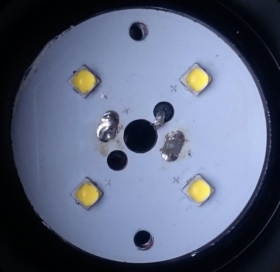
The delaminating traces are not so nice! Hope that it will be possible to reflow new LED´s on the MCPCB at least one or two times before the delaminating gets to bad!
I hope that the delamination was caused by my impossibly hot 80W solder iron, and that normal reflow temperature does not cause it, and that it can handle multiple reflows without problems.
Just to note, I'm concerned about what djozz experienced, but I have worked with the ThorFire predecessor to this MCPCB in the round 1 and round 2 prototypes and didn't have the problem, or at least noticed it. I de-soldered/soldered wires and removed LED's, reflowed others on.
I use my Hakko at about 370C or so.
I used to see SinkPAD and Noctigons exhibit this separation if I went to hot on the hot plate, now I use a hot air station at 370º C and have zero issues.
If temps above 300°C is not a problem reflowing LED´s should be no problem. But maybee someone can test the last batch of MCPCB´s. After all this MCPCB is not cheap or easy to get if damaged.
I've been bad as of late - I've been reflowing LED's with a small torch, heating the underside of the MCPCB. Gotta keep it under control of course, very careful with the heat, but seems to work ok for me. Only problems I've had with MCPCB's has been with the KD ones - not full delamination but on edges of traces, they were pulling up.
True - we should do more testing on these. Not only are they not cheap, but may not be possible to replace directly. Dunno if ThorFire will offer these for sale or replacement. Other MCPCB's could be used of course, but with some modding work I'm sure.
My ledboard is OK, after getting the wires off and on looks good
But I have a modest simple 45W iron.
I meant the threads on the screws.
With two holes - slightly misaligned, as shown in the picture above — notice the oval opening
a smaller diameter screw (as described above) will, yes, fit all the way down through to (barely) engage the threads in the lower hole
and it can be tightened because it’s wedged in, but it is going to be in contact less than halfway around each of the holes and barely engage the threads
It’s just the kind of thing to notice on a handmade sample that shouldn’t happen on a production line where they’d use a jig to align the pieces before drilling and tapping.
I was wondering ( cuz i see little things like that )
If the emitters was turned 45 degrees in their location so a corner faced towards the center hole, would that have a impact on beam profile, or would it just be me overthinking stuff again.
I think your assuming something that is not happening. There are no oval openings, it’s just the shadow thats making it look oval.
Maybe someone can take another picture with the light source overhead to better show the screw holes.
See djozz’s comments on this at
and at
Since he thinks it’s no problem, I’m happy. I trust his judgment.
Just thinking ahead, I assume any LED is going to be replaced in a year or two with something better, so watching for possible issues.
As he says a longer nut and a bolt would solve any problem.
The shelf is thick enough that there is a decent amount of threading that will hold up to the several times that the ledboard will be screwed down after a led swap.
Btw, with the currently available leds I’m not sure I can think of a better led for the Q8 than what is in these prototypes, the combination of good tint (it really seems 3D to me), great output and even beam profile without obvious tint shift just does it for me, also in actual use. Both 219C and XP-L2 have such low voltages that they will draw way more current than the XP-L with not that much more output, with all the extra stress on the light that cones with that. And the XP-L2 will never give the nice beam profile that we have now.
I’m on the list for one Q8, I will try something high CRI in it but I’m not sure that I will prefer that over the high output proto3.
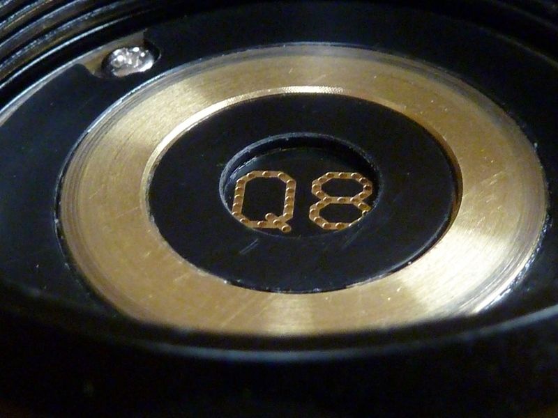
Could someone let me know the width of the contact ring on the underside of the driver?
I just want to check that the buttons on the Fasttech 30Qs aren’t too wide.
The contact ring sticks out over the plastic, the width of the buttons will not matter. You could ask then why there is a plastic ring at all, apart from that it looks good I would not know.
I would think that with the plastic insulation ring present it wouldn’t really matter how wide the button tops are, the ground ring is below the level of the positive contact anyway looks to me like. Could be wrong, can a prototype holder confirm?
From OP
Thanks, just had a closer look at the photos and I see what you mean.
In height, inner black plastic is definitely lower than the brass. for the outer, boy, I've been fingering the feel (?) for 5 mins and it's hard to tell. That's my pic of this light, and the pic seems deceptive. I'd say the brass is ever so slightly higher accept maybe where the screws are - feels bout even.
I don't have a lot of feel left in these fingers anyways  .
.
This thread is over 7000 posts long, so forgive me if this has been asked.
Does the Q8 still run with anything between 1 and 4 cells? Other than run time, does using less than 4 cells affect maximum brightness? Thanks.
It’s 4 cell in parallel so you can use any number of cells you want.
Maximum brightness, or amp draw, is about 20 amps so 4 cells share that at 5 amps each. The fewer cells you use, the more voltage sag you get and that results in less lumens. Because max lumens is gonna happen at the highest voltage.
I’m sure one or two cells can get close to max brightness, but not all the way max like 4 cells can.
Does that answer your question?