Assuming it is DD, the energy will be the same in both cases, regardless of good or bad thermal path.
The difference is that when it has a bad thermal path then more heat remains in the MCPCB and less transfers to the body.
The total energy dissipated is still the same, but there is more energy stuck in the MCPBC than in the body (compared to a good thermal path, where the energy can easily transfer from the PCB to the body.)
Since the MCPCB has a lot more energy and doesn’t transfer as much to the body, that results in a higher temperature at the PCB.
In the opposite case where the thermal path is good, the temperature difference becomes less, so the PCB and body are closer to the same degrees.
That means the MCPCB is cooler and the body is hotter. (but the MCPCB will always be at a hotter temperature than the body)
Enderman,
IF it is assumed that the energy input is the same for each case, and we disregard the decrease in efficiency of the LED at higher temperatures, then the body of the flashlight will be the same.
You are right, there will be a higher delta T, but there will also be a higher thermal resistance, so the heat flow will be the same! (Double the Voltage and Double the Resistance in a simple circuit, and electron flow is the same)
What the heck are you talking about?
This has nothing to do with voltage or current.
If you have 1kj of energy on a piece of copper with a bad thermal path to a chunk of aluminum, the copper will be much hotter than the aluminum.
If you have a good thermal path, the copper will only be slightly hotter than the aluminum because the energy will transfer between the pieces easily and equalize.
That means the copper temperature decreases and the aluminum temperature increases.
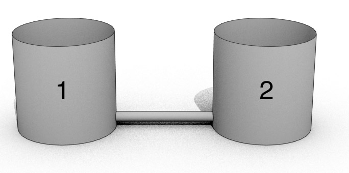
Think about it as two buckets with a tube running between the two.
Well, first off, where did NeutralFan take the measurements? I don’t see where in the OP he states the location. If it is the outside body, close to where the shelf contact is, then with better heat transfer you would think the outside body would take on more heat, keeping the MCPCB cooler in the process. I’m guessing it will be slightly hotter but I doubt it will be noticeable.
Cool project though, you sound like me. I always want to do things as efficiently and effectively as possible, the first time.
The LED produces heat and light.
The heat has nowhere else to go then to the body.
So, the efficiency of the LED basically determines the heat going to the body.
The efficiency suffers when there is a poor thermal path (high delta T) because the LED will then operate at higher temperatures.
At a certain point (saturation) the delta T is high enough to stop the LED from getting even hotter and thus all of the generated heat will be transferred to the body.
When I put the LED MCPCB back on the shelf over the thermal compound, I first slowly pressed down evenly and gently. Eventually I pressed hard and slightly rotated the MCPCB clockwise and counter-clockwise by approximately 5-10 degrees.
I took the temperature measurements using an infrared thermometer. I pointed it at the body of the flashlight and found the hottest spot. The flashlight was tail standing in turbo mode. The hottest spot was near the top of the head, just below the bezel.
I agree with this and that was my rationale for the experiment. Assuming a better heat transfer from the LED MCPCB to the shelf using the dot method versus the spread method, I would expect the temperature to increase faster near where the shelf is located.
The driver was in direct drive turbo mode and the same battery was fully charged before each set of measurements.
In those tests the thermal path seems to turn out well because the LED board is clamped down on the cooling body.
‘Bad cooling’ is not tested there.
But you can see the differences better in tests between DTP and non DTP boards.
In those tests the thermal path seems to turn out well because the LED board is clamped down on the cooling body.
‘Bad cooling’ is not tested there.
But you can see the differences better in tests between DTP and non DTP boards.
[/quote]
Yeah but it’s still bad cooling, you do that to a computer and it will instantly overheat.
It’s just that LEDs don’t make a lot of heat unless you push them hard.
I was a little surprised by the results. It makes sense that the middle dot method is preferred for applying thermal compound. After all, the spread method can lead to air gaps which is not good. I only measured the temperatures up to 4 minutes since I was genuinely concerned that the LED would get too hot if I went longer. I did not want to damage the LED due to not applying the thermal compound correctly.
Was the time I spent to change out the thermal compound worth it? In hindsight I would say no. But since I didn’t know, applying the thermal compound the correct way gave me piece of mind. That in itself is worth the hour or more I spent on this.
Perhaps with a more powerful flashlight the results would have been different, and probably even more critical on a computer CPU, but it appears that the 2 methods I used to apply thermal compound was equally effective.
Here are the results again from the surface spread method:
Start – room/flashlight temperature at 67 degrees Fahrenheit
1 minute - 84F
2 minutes - 95F
3 minutes - 104F
4 minutes – 113F
Here are the results after I used the middle dot method, look familiar?
Start – room/flashlight temperature at 67 degrees Fahrenheit
1 minute - 84F
2 minutes - 95F
3 minutes - 104F
4 minutes – 113F
Thanks to all that gave their predictions and knowledge about thermal compounds. I took a thermal dynamics class back in college, but that was many years ago and I don’t recall any mention of thermal compounds. Certainly many of you have a lot of knowledge about this and I continue to learn from BLF.
some of the best negative results I’ve seen lately
acutely portended by most
so as long as the surfaces are flat, then it’s superfluous to add compound?
The only reliable way to measure a miniscule thermal difference vs LED junction temp is to monitor LED voltage by at least 3 decimal digits. This is one of the simplest method used by advanced LED driver to regulate temp or to maintain true constant brightness/power.
With low power stuff like most LEDs yeah.
If you’re like me with an XHP70 at 12A making 100W of heat, then no you certainly need thermal paste to keep the LED from melting.
There’s no harm in adding thermal paste though just to be sure.