With two holes - slightly misaligned, as shown in the picture above — notice the oval opening
a smaller diameter screw (as described above) will, yes, fit all the way down through to (barely) engage the threads in the lower hole
and it can be tightened because it’s wedged in, but it is going to be in contact less than halfway around each of the holes and barely engage the threads
It’s just the kind of thing to notice on a handmade sample that shouldn’t happen on a production line where they’d use a jig to align the pieces before drilling and tapping.
I was wondering ( cuz i see little things like that )
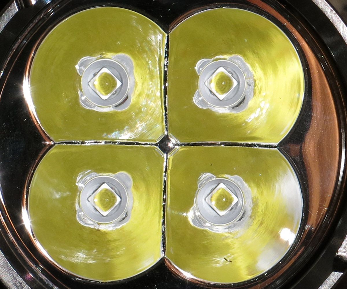
If the emitters was turned 45 degrees in their location so a corner faced towards the center hole, would that have a impact on beam profile, or would it just be me overthinking stuff again.
The shelf is thick enough that there is a decent amount of threading that will hold up to the several times that the ledboard will be screwed down after a led swap.
Btw, with the currently available leds I’m not sure I can think of a better led for the Q8 than what is in these prototypes, the combination of good tint (it really seems 3D to me), great output and even beam profile without obvious tint shift just does it for me, also in actual use. Both 219C and XP-L2 have such low voltages that they will draw way more current than the XP-L with not that much more output, with all the extra stress on the light that cones with that. And the XP-L2 will never give the nice beam profile that we have now.
I’m on the list for one Q8, I will try something high CRI in it but I’m not sure that I will prefer that over the high output proto3.
The contact ring sticks out over the plastic, the width of the buttons will not matter. You could ask then why there is a plastic ring at all, apart from that it looks good I would not know.
I would think that with the plastic insulation ring present it wouldn’t really matter how wide the button tops are, the ground ring is below the level of the positive contact anyway looks to me like. Could be wrong, can a prototype holder confirm?
In height, inner black plastic is definitely lower than the brass. for the outer, boy, I've been fingering the feel (?) for 5 mins and it's hard to tell. That's my pic of this light, and the pic seems deceptive. I'd say the brass is ever so slightly higher accept maybe where the screws are - feels bout even.
I don't have a lot of feel left in these fingers anyways .
It’s 4 cell in parallel so you can use any number of cells you want.
Maximum brightness, or amp draw, is about 20 amps so 4 cells share that at 5 amps each. The fewer cells you use, the more voltage sag you get and that results in less lumens. Because max lumens is gonna happen at the highest voltage.
I’m sure one or two cells can get close to max brightness, but not all the way max like 4 cells can.
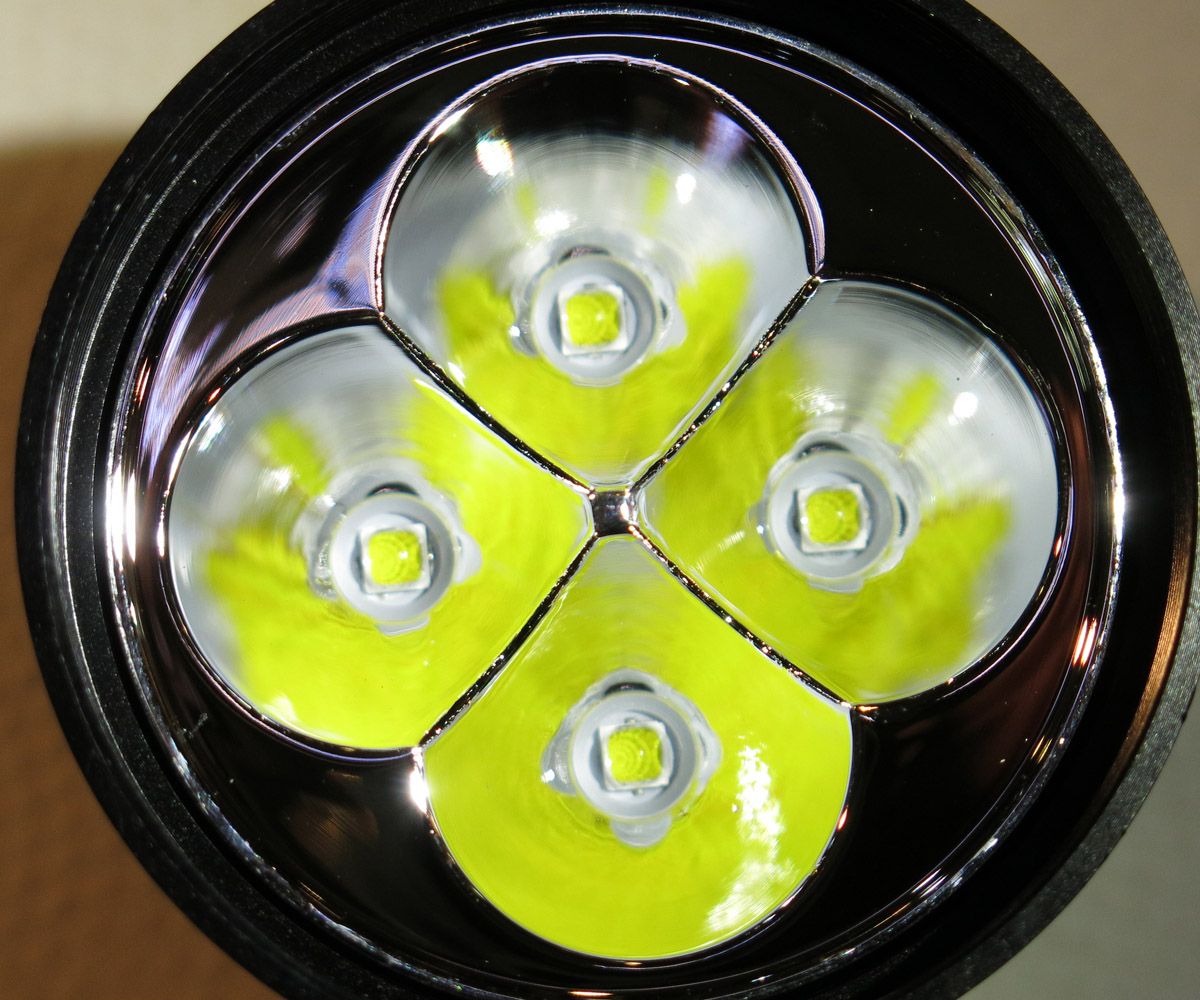
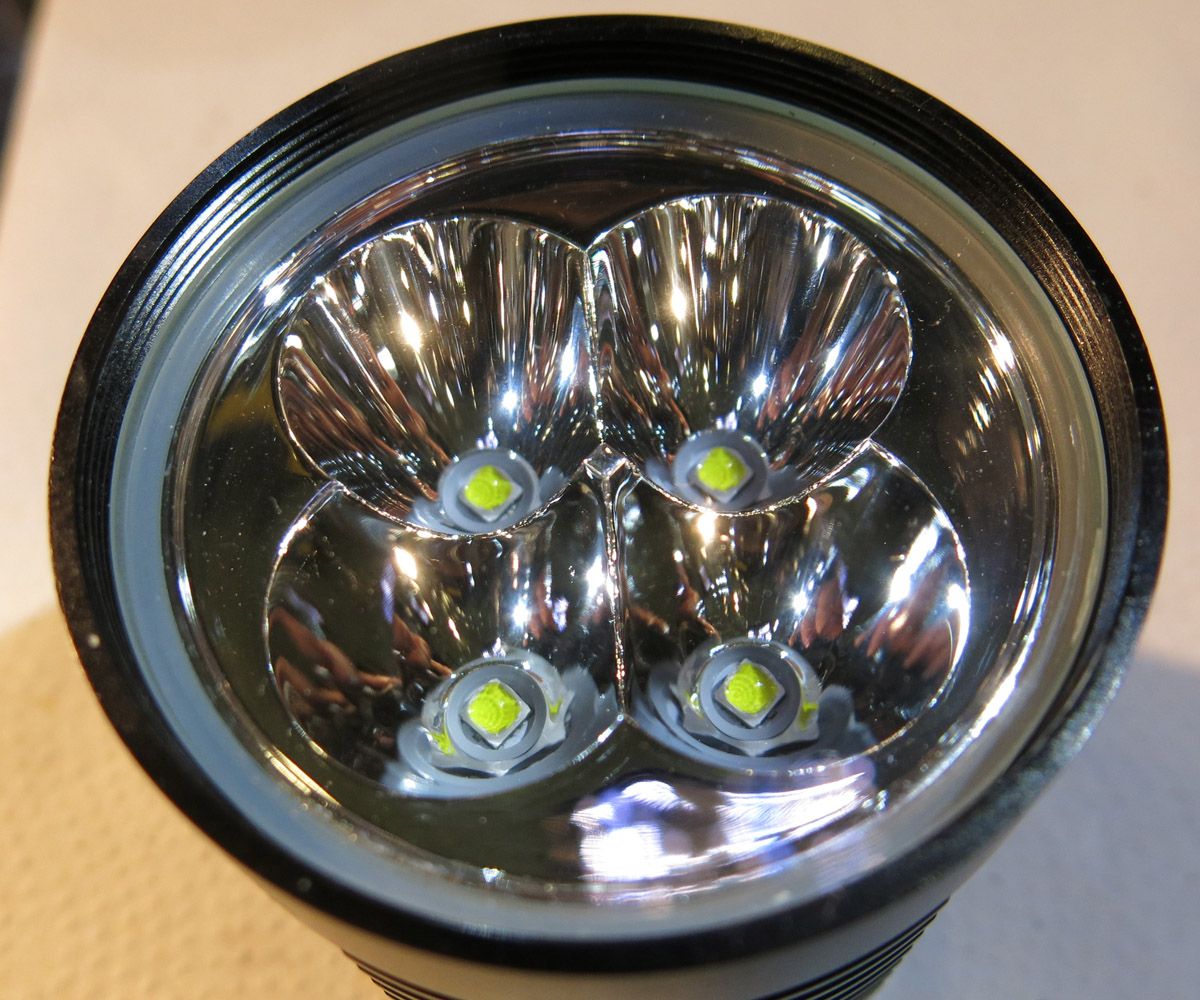
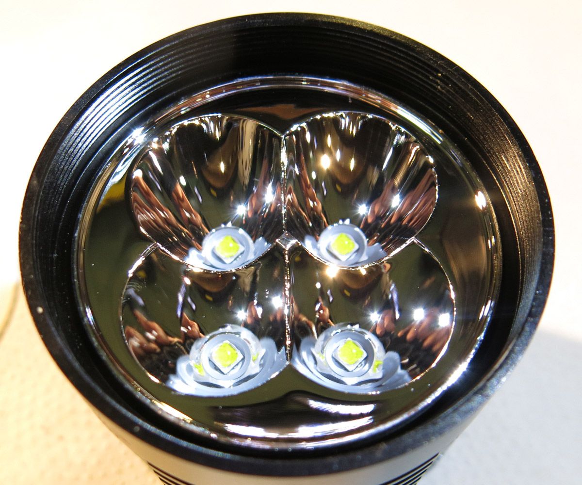
A few pictures from the sample light I received.
Firstly when I first inspected the light the most disappointing part I could find was the led alignment. It did not seem to affect the beam pattern at all but non the less they were not perfectly aligned.
When reassembling the light after taking these pictures I was pleasantly surprised that the leds were near on in perfect alignment with the reflector openings. I guess the reflector twisted slightly when the centre screw was tightened
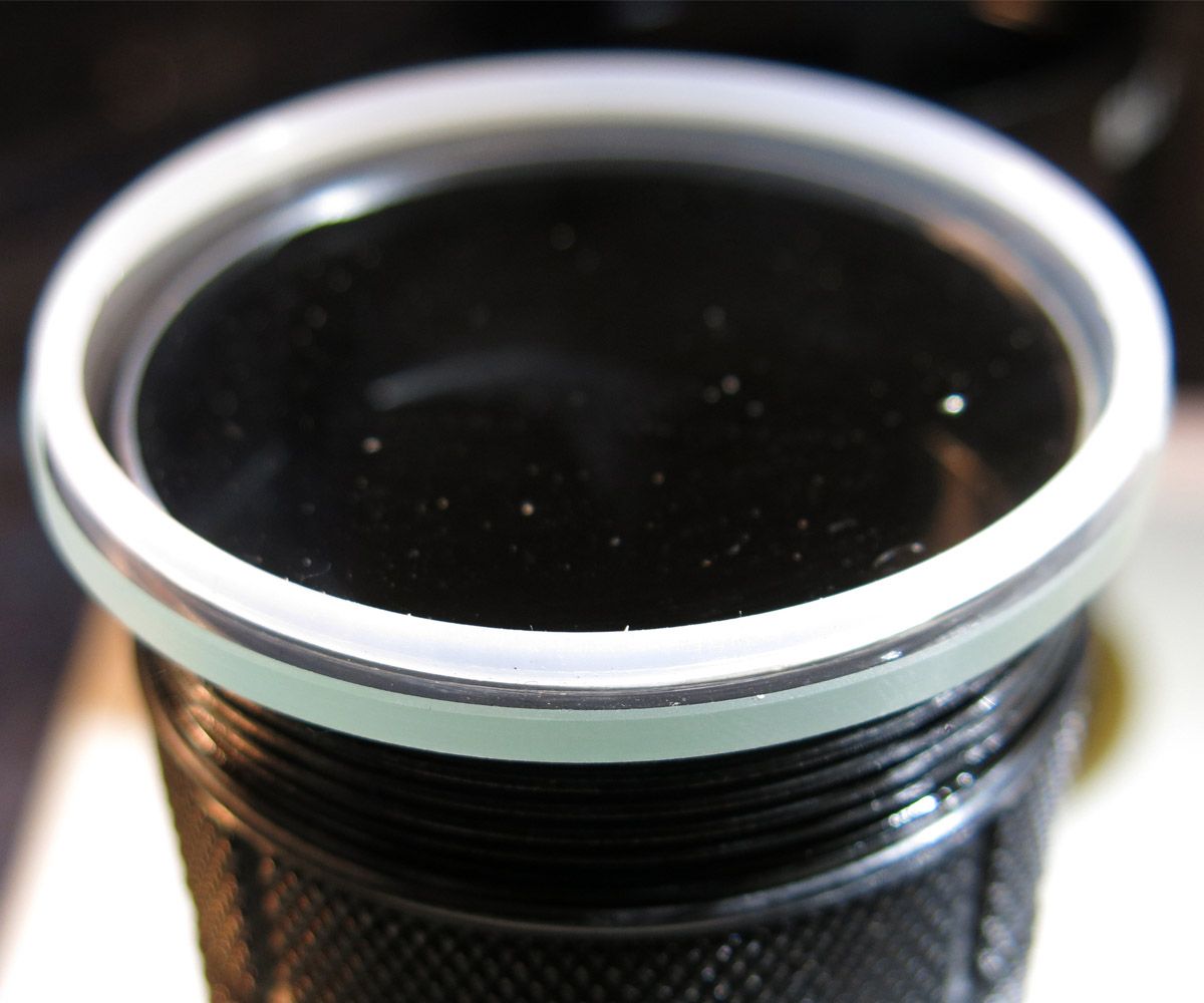
The lens sits on a softish white oring.
The oring itself sat on a shelf with enough of the oring sticking above the reflector that should give a good seal against the glass lens. Saying that I would choose another light to go swimming with.
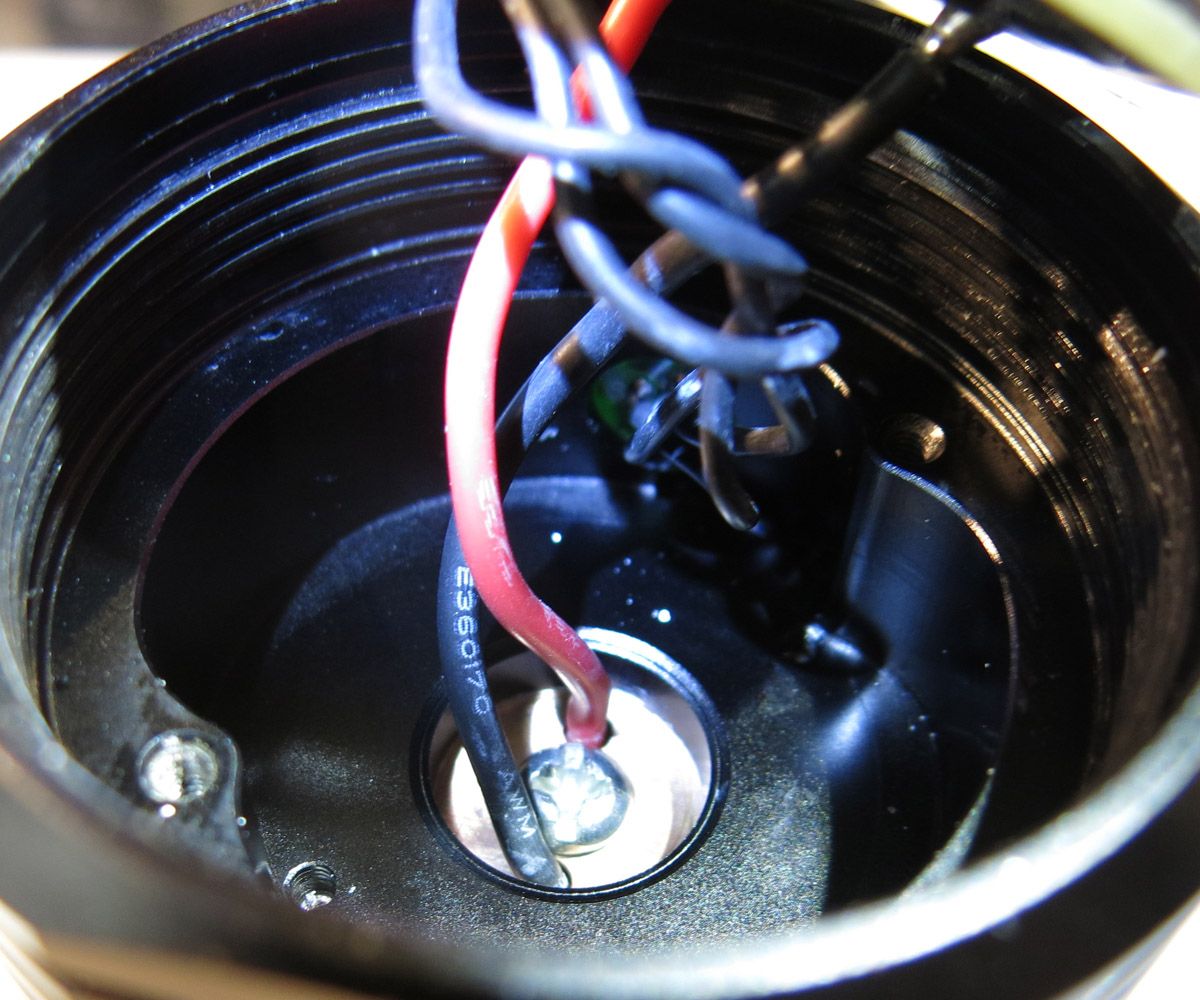
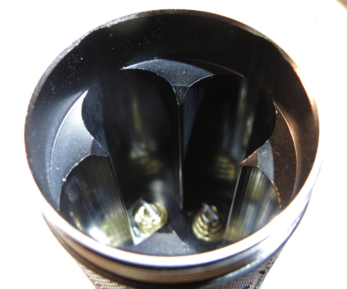
I loved the way the driver was held in with two screws having seen anough press fit drivers loose there effective press fit after being removed and replaced a few times. Here you can see the kidney shape with the threads that hold the driver in. Just the shape itself would have to add to the strength of the head and add effective heat sinking as well. The retaining screw for the reflector can be seen in here in the middle of the head along with the thickness of the MCPCB shelf. It would have to be around six mm or a 1/4’’ in thickness.
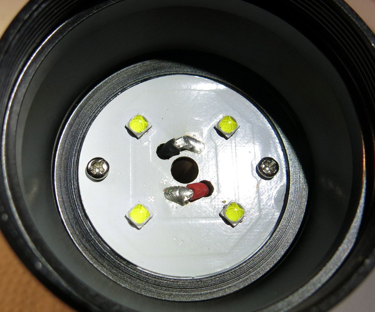
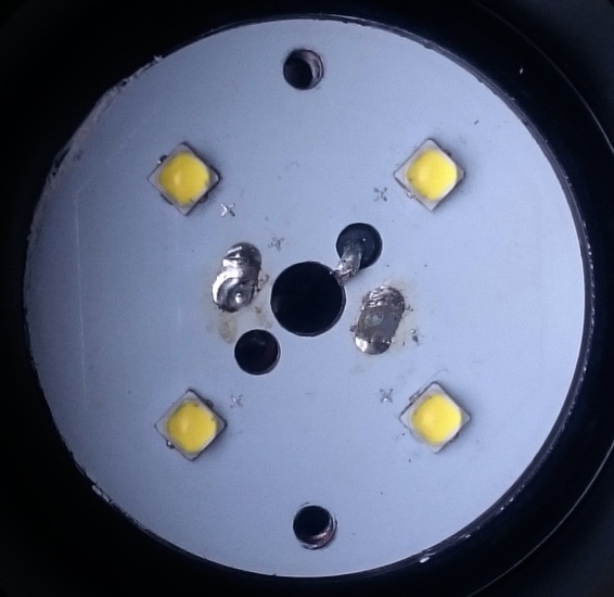
With the reflector removed the MCPCB can be seen along with its two retaining screws. It sits neatly in its own machined space.
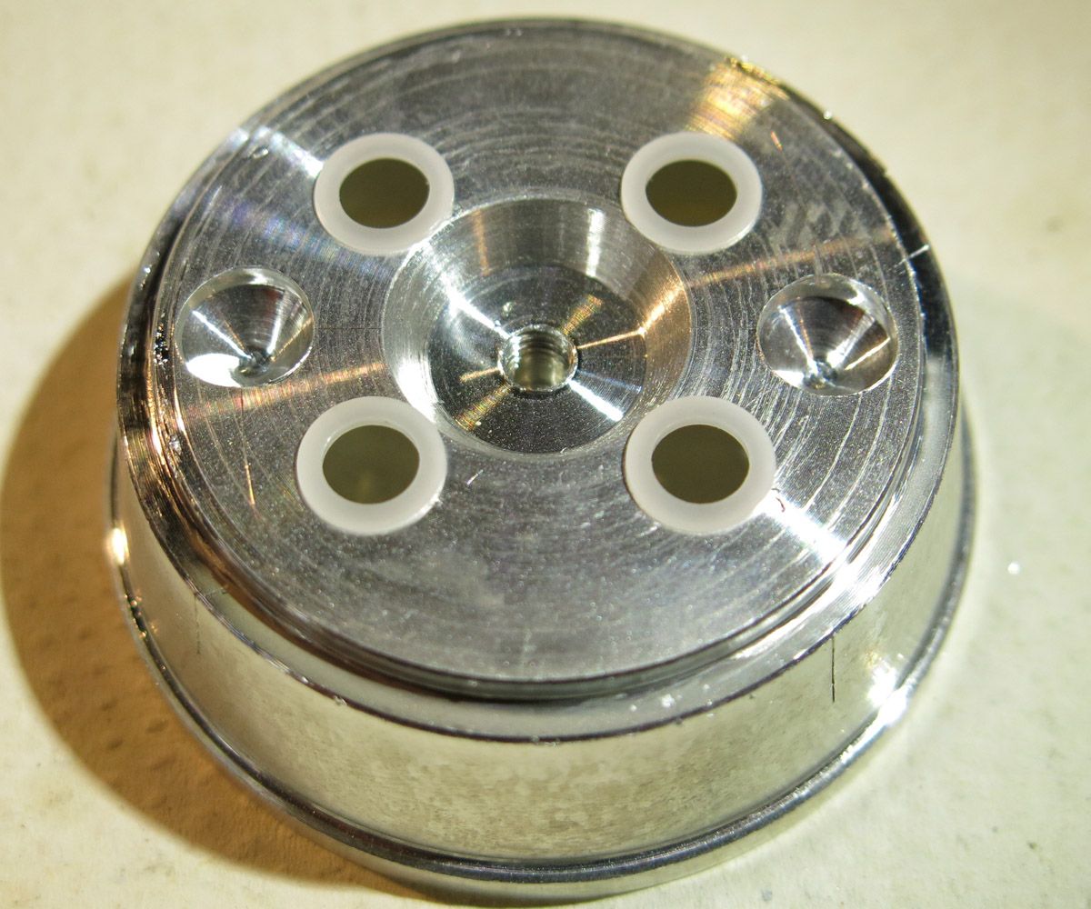
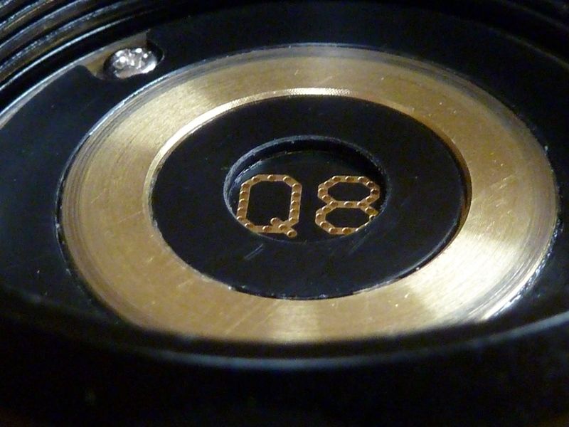
The base of the reflector shows the machined hole in the centre for clearance on the positive and negative wires where they solder to the MCPCB. There is no chance of shorts here. The outer machined holes are for clearance on the MCPCB retaining screw heads.
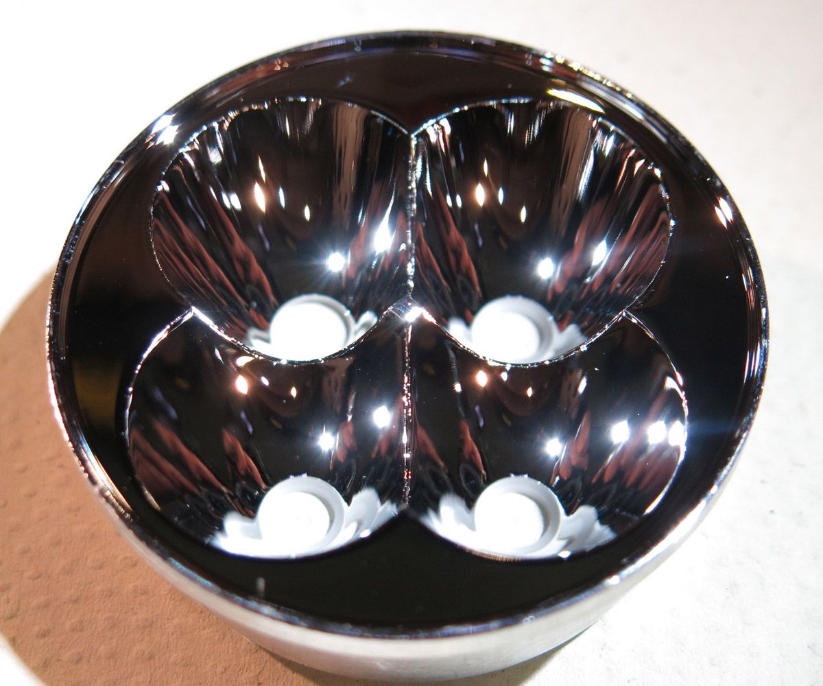
No visible flaws could be seen on the working side of the reflector.
The lens appeared to be plain glass. It was a meaty 3mm in thickness and 55mm in diameter. The oring was 2mm in width.
The worst part of the light I could find was the top edge of the holes for the battery’s in the battery tube. There were no burs as such but the edge was reasonably sharp.
Whats there not to like about this light? In my view nothing really. One thing I should also mention was when I swapped the negative end of the light over for the proto I built with spring bypasses the output rose sufficiently enough that I will mod this light with spring bypasses as well.
With the design of the light the way a light should be and with the trend setting modes on the driver of which Tom seems to have spent every last second and then more putting together and problem solving behind the scenes I would like to publicly say thanks.
It has become my go to light for 90% of my torch needs.
This really is a bargain in todays world of torches and no this is not a paid advertisement.
Think of it like this. The stock battery on your car will crank the engine over at normal speed because it has minimal voltage drop due to its size.
If you hook a small motorcycle battery to your car it may crank it, but it will spin slower due to the bigger voltage drop when under the same cranking load.
So 4 good cells in the Q8 on turbo (20 amp load) may drop the voltage from 4.2 volt to 4.1 volt.
Now let’s say you put one battery in that is 20 amp capable. Put the light on turbo and you will get a bigger voltage drop. It may drop to 3.5 volt and theoretically still pull 20 amps. The amp draw will actually be lower, but let’s keep it the same for this example.
20 amps at 4.1 volts is 84 watts of output.
20 amps at 3.5 volts is 70 watts of output.
So a single battery may still give you turbo, but it is not the max turbo you’d get from 4 cells.
Now getting back to the amp draw, the FET driver is only going to put out what the battery can deliver. So a single cell under heavy load is going to have lower voltage as well as a lower amp draw. I don’t know how much lower as I’m still learning about FET drivers.
I’m sure some one can step up and measure the current draw with a single battery and tell us how low the voltage actually drops (I’m just guessing 3.5v or so) as well as how many amps it draws. I’m curious about actual numbers myself.
 .
.