The Imalent DM 21 has driver and USB charger in the tailcap without wires running through the body. It is possible. Driver, battery and switch are all in series, so it shouldn’t matt where these component are in the string.
I’m not sure that’s true. They’re all in series along the negative current path, but the driver has to have access to Vcc too, just like the emitter. So that side of the circuit is parallel.
Nope.
Most drivers have + and - contacts for the battery, then + and - wires for the LED.

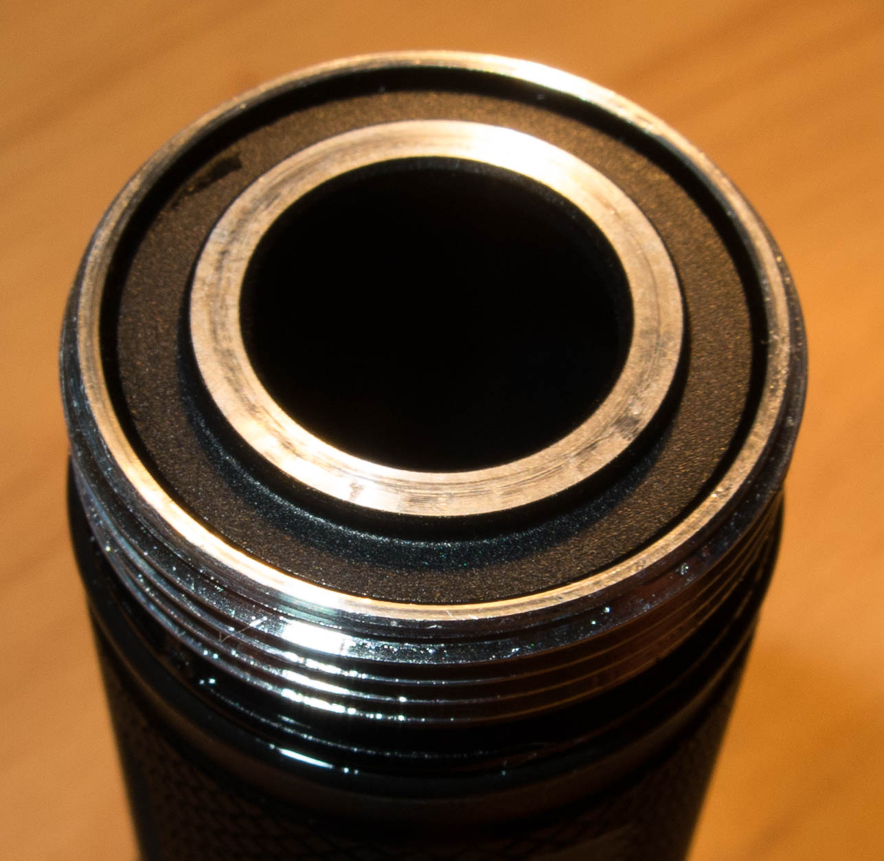
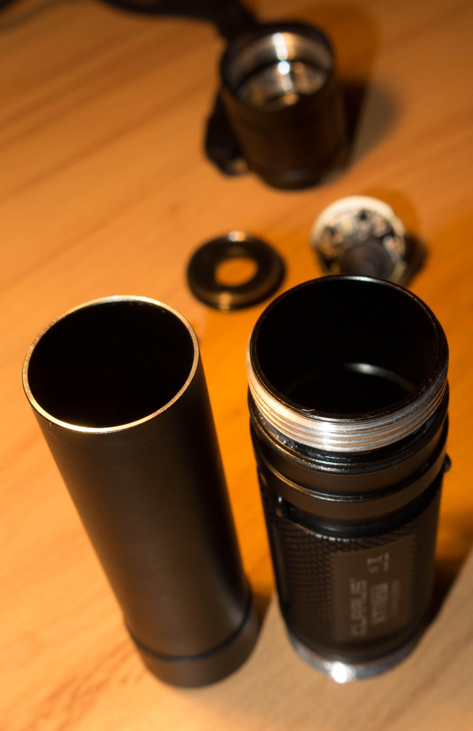
It is easily doable with 2 tubes for the driver positive and LED-, like Klarus build their lights
there is no need for the LED positive cable to go to the driver, as its connected with the battery +
It can be done without any cables or double tube, with a battery that provides positive and ground to the driver in the tail and use a p channel fet for the LED+ and battery ground for LED-

Or the HDS method with a wire in the body.
The Imalent DM21T does not have a wire going to the head. The driver (with brightness control knob) and usb charging are in the tail. It can be done without a wire running from driver to battery +.
The one thing the DM21T is missing is LVP. The driver does not have direct access to the battery voltage. LVP in their design would require a more complicated driver that approximates battery voltage by measuring current and knowing the Vf of the LED at that current.
This is not true.
Maybe on some very basic drivers, but not the large majority.
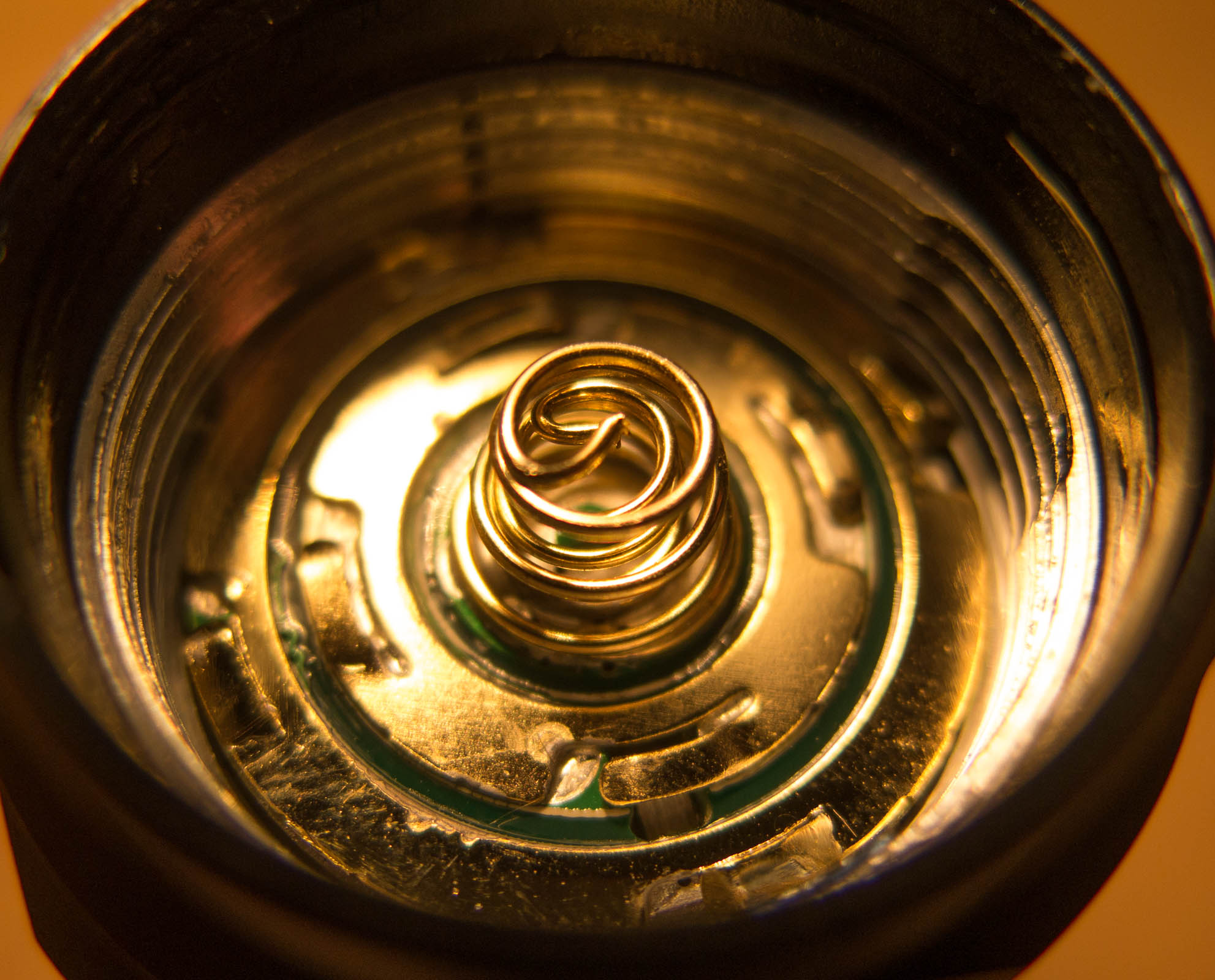
Just take a look at the PCB, you can see it does not just go straight through.
So you see it can be done, but all that do charge a hefty price for their lights
For Narsil and Bistro based drivers that allow temp stepdown using the MCU it still is best to have led and driver close together or a temp sensor needs to be installed, adding complexity in parts and assembly AND sacrificing a MCU pin for the read out.
FET is not driver :student:
???
I am talking about BLF developed firmware that has the option to use the temp sensor build into the MCU for user calibrated thermal stepdown vs using extra parts to measure temperature.
It is quite useful to have the MCU located in the area where it can actually sense temp ![]()
You are talking about pretty names that some useless parts of firmware used to call here. Simple thermal resistor on pcb can do this job (thermal stepdown) better (much better) than mcu-integrated sensor (regardless what firmware do you use). There is no sense in applying so much efforts in firmaware which should manage so simple hardware.
FET is not driver. You can not garantee any value. Each of them will be always different. Simple things that are usual printed on brand light boxes - smth like runtime@100 lumens - cant be calculated, because fixed mods do not exist.
Good Discussion! ![]()
About the “modern/fancy drivers need direct access to + voltage” argument, though …
Couldn’t there be a “leakage path” up at the LED, so the driver is never really without current?
Then the driver, or micro, or whatever you call it (the active electronics) will have some juice to run on, without a direct connect to the + terminal.
Hm. Sounds a bit negative.
I am not talking about FETs just stating hoe Narsil and Bistro achieve thermal stepdown without the need for a thermistor.
Yes as I wrote a dedicated part for measuring can be done.
Yes as you write, there is a big difference in how each individual driver without it measures temp.
(I have read it is the MCU doing the measuring not the FET)
Hence the clever workaround, one selects thermal stepdown instead of the default timed stepdown and the light starts on turbo, one selects the desired stepdown temp and it doesn’t really matter that other same hardware drivers measure temp different for it is setup based on that individual unit.
So i don’t disagree with what you say, I merely explain why IMHO things are done how they are done in the lights I know a little bit more about ![]()
This Costco Duracell 700 lumens flashlight has driver circuit in a tail:

Batteries, LED and driver circuit are in serial, but it needs a 24 Ohm resistor parallels with LED to pre-feeds power for driver circuit. Circuit likes that will “eat” some more energy (~ 200mA) from batteries when turns ON (because of current goes through LED and resistor at same time).
Yes it can be done (at least with a linear driver). It is a DC circuit, current is flowing in one direction so Pos+ Voltage is available anywhere in the circuit without any extra wires. It is this principle that allows the illuminated tailcap to work.
So why isn’t it popular here?
- It makes a bigger tailcap necessary, which can be really ugly and is not accommodated by many hosts.
- Driver modding started with Qlite drivers (which have a Pos+ battery connector), and evolved from there.
- See below:
Ultrafire UF10 and UF9 have Drivers in the tail and they are my coolest 16340 lights. You can drill the tube to fit a 18350, I made it on three lights.
Robert
An illuminated tail cap is literally just another LED in the circuit, that’s why it only needs to be in line to work.
For any kind of modern not-super-basic driver there needs to be separate positive and negative to both the driver and LED for it to work properly.
Stuff like LVP, battery indication, cc regulation, etc…
That stuff is not possible if you simply have battery~~driver~~>led->battery.
In this case the driver would literally just be an in-line resistor, it would not have any other functionality.
With our drivers the battery positive does “pass through” to the LED, but it’s still connected to the driver. The MCU needs the connection to the positive to work.
So it’s impossible to have a driver without +
Technically you can, it would basically be the same thing as a resistor.
Maybe it would be possible to have it switch between different resistances too to change the brightness.
But for most drivers, the advanced kind we use in flashlights, it would not work (not properly, at least) if you connected + directly to the LED bypassing the driver.