Here's a go at my first time modding & having anything to do with LEDs.
Wanted a set of Aux lights for my motorcycle and most cheap off shelf lights had lighting modes which switches when you toggle the on/off switch, which isn't practical while on the road, I wanted something that I could quickly turn off, will passing other vehicles and return to the set brightness settings.
So I decided to try building one, it's not completed, left the control buttons, but basically most of it runs now.
Still deciding what Amps to run them at for full power. (Please do advice or give any suggestions)
So here's a list of items i purchased & their cost. I bought mostly off Taobao.com, a chinese site which is really cheap.
I'm driving the LEDs at this settings:
3x6V = 18V @ 2.75A
3x12V = 36V @ 1.3A
I'm thinking if I can push the LEDs to these settings and if the lights can be in working temps, any recommendations?
18V @ 4.5A
36V @ 2.25A
Light bodies/case
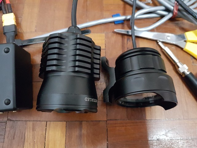
Body 1 on the left, Body 2 - smaller one on the right.
Body 1
$25usd - comes with mounting brackets/clamp - Claimed 30w 3xXM-L2
https://world.taobao.com/item/44000857226.htm?fromSite=main
LEDs were wired in series, which made it easier when I am going to power 3 xhp50s, & i could reuse the reflectors.
Good thing about this light, it doesn't have any lighting modes, just on/off.
Measured off my LiFePo4 batts 13.5v drawing 0.7A... Works out to be about 3W per bulb. Looks way dim, so I'm not surprised.
Body 2
$14usd - just the body
https://world.taobao.com/item/551266403953.htm?fromSite=main
7 LEDs, wired in parallel. Really cheap. Couldn't remember the current draw I measured, but this was way dimmer than the first light i got(Body 1).
There is no way i could reuse the MCPCB as well so i ordered 3 XHP50 mounted on copper MCPCB, & got 3 lenses for it as well as the original reflector doesn't line up with 3 stars inside.
LEDs
3x XHP50 mounted on all copper MCPCB 12v
$3.60usd each - total $10.80usd
https://item.taobao.com/item.htm?spm=a1z09.2.0.0.1f30a53fVpRRRZ&id=525526937942&_u=41ui9qg9a729
3x XHP50 bare
$2.70usd each - total $8.10usd
https://world.taobao.com/item/552921202102.htm?fromSite=main&spm=a1z09.2.0.0.1f30a53fVpRRRZ&_u=41ui9qg900bc
3x Lenses
$0.22usd each - total $0.66usd
https://world.taobao.com/item/35720272414.htm?fromSite=main&spm=a1z09.2.0.0.1f30a53fVpRRRZ&_u=41ui9qg9ff53
Some photos of the MCPCB & lenses
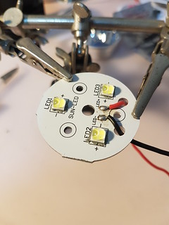 Reflowed the XHP50s onto the original MCPCB of Body 1
 Tested out the freshly soldered XHP50s to make sure i didn't destroyed them. 18v @ 1.4A, and left it on the floor with the LEDs facing down (it was too bright) and after 30s smelt something burning, and found my wooden floor burnt.
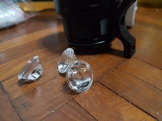 8 degree lenses
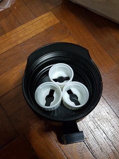 Checking fit of lens holders into Body 2
Electronics
Next I figured i needed a way to control the lights. Settled with an Arduino Nano and did some trial & error on the programming for it to work.
As on choosing how to drive (Buck or Boost converters) the LEDs & what Voltages should I use i took these into considerations.
The motorcycle electric system can range from 12-14Vs, so i decided to wire the 6V leds in series for Body 1 (not much of a choice as the stock was in series) & 12V LEDs in series too for Body 2.
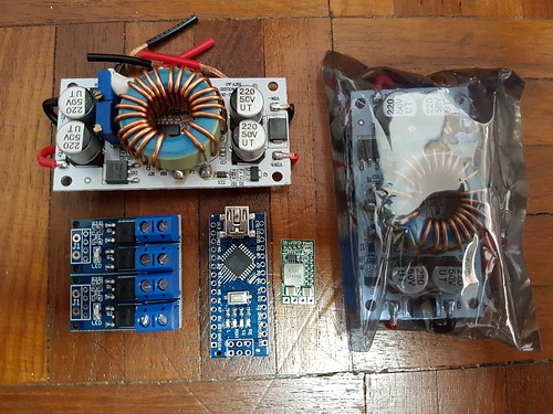
As space is a constraint as well (wanted it to fit all nicely under the seat) I settled with 2x 250 Watt Boost converters.
2x 250W Boost Converter
$3.70usd each - total $7.40usd
https://detail.tmall.com/item.htm?id=525632257737&toSite=main
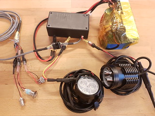
These are the white board & the one in the static bag in the photo above.
I had to have 2 boards cause 1 Body is running at 18v, the other 36v. I figure there will be efficiency issues, but figured a drop of 20% is acceptable.
Note: The module has a limit of 10A input & 10A output. If input is >8A, cooling will be required, or if output is >6A cooling is required.
So those factors I had to constantly keep in mind to no burn my bike down.
2x PWM Switch (I believe it's a MOSFET?)
$1.16usd each - total $2.32usd
https://world.taobao.com/item/540406913795.htm?fromSite=main&spm=a1z09.2.0.0.1f30a53fVpRRRZ&_u=41ui9qg9eb89
They are the 2 small boards connected (i haven't broken them off) in the lower left corner in the photo above.
Spec'ed at 400W 30A. Though recommendation room temperature upper limit is 15A. A bike internal working temp, I'm under the assumption it's 85 degrees celsius.
I'm using this to separate the driving voltages/current from the Arduino controller. The Arduino will have 2 separate PWM outputs to each of these, so in future, if i wanted to control either lights individually, i could.
Arduino Nano
$1.20usd
https://world.taobao.com/item/544996293668.htm?fromSite=main&spm=a1z09.2.0.0.1f30a53fVpRRRZ&_u=41ui9qg9ef3a
This is the board just on the right of the PWM switch in the photo above.
I was thinking of using the ATtiny, but I couldn't wrap my head out regarding the pin outs & PWM stuff, wasted a few days on it and couldn't get it to work, so i reverted back to the Arduino Nano.
I have 1x On/Off switch (with led indicator-which i power with the Arduino PWM to glow, the brightness of the glow corresponds to the current brightness settings of the main LEDs), 1 momentary push button ( so i can quickly turn off the lights while held down, if the main switched is off when this is pressed - i set it to turn on, sort of a 'high beam'), 1 Linear Potentiometer (to control brightness).
DC-DC Buck convertor
$0.60usd
https://detail.tmall.com/item.htm?id=548559287443&toSite=main
Small green board just beside the Arduino Nano in the photo above.
I needed a power source to power the Arduino, and since the Arduino doesn't need too much, this is sufficient. I must say this board is pretty versatile. It's tiny at 20 (L) * 11 (W) * 5 (H) mm! Also it has preset options that you just solder short to have it fixed at that voltage output (1.8V 2.5V 3.3V 5V 9V 12V), instead of configuring it with a multi-meter.
Board is set at 9V & connected to the Arduino Nano's Vin
Switches & Buttons
Switch with LED indicator
$5.20usd
https://world.taobao.com/item/37243475584.htm?fromSite=main&spm=a1z09.2.0.0.1f30a53fVpRRRZ&_u=41ui9qg9b70d
Stainless steel, IP67 rated (there are IP65 & IP67, not sure which one i got), 3-8V LED
Push Button
Stainless steel, IP65 rated
Potentiometer
Though it's not the most expensive component so far, but i can't help it's way expensive for just a little dial.
But it's the only one i could find that is IP67 rated, since it's going on my bike's handle bars exposed 24/7. :(
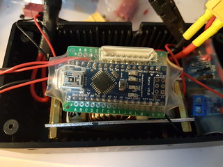
Arduino Nano mounted to a PCB and wired to a connector to link up to the Controls using a 8 core data cable.
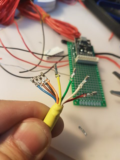
Crimping the ends of the data cable for the connector.
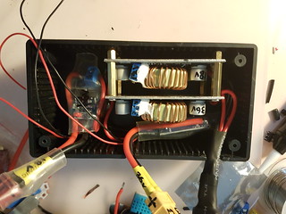
How the Boost convertor & PWM modules fit into the small hobby box I have. Note the lack of active cooling, I'm figuring that most of the modules i'm running at less than 30% of what it's rated, so i can get away with heat management.

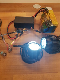
Here's how the Bodies with the mounted LEDs looks like.
Body 1 is the one on the left, it looks the Best, close to stock just with XHP50s in them. The light beam is much narrower than the other Body as well.
Mounting the MCPCB on Body 1 is easiest as well, as I just had to use some thermal paste (>6.0W/m-k), the metal reflector has a screw that goes through the aluminium housing that clamps everything down. But only concern is the MCPCB is Aluminium & heat dissipation
Mounting the 3 star 12v LED boards on Body 2 is trickier and honestly I'm not sure if it will hold up to the abuse & vibrations it will see on a motorcycle. The 3 star boards are first place down with thermal paste (>6.0W/m-k), then the spaces around are filled with some silicone that apparently is used for electronics, it has a rating of >1.5W/m-k ( not sure if this is enough?).
Finally, I'm driving the LEDs at this settings:
3x6V = 18V @ 2.75A
3x12V = 36V @ 1.3A
I'm thinking if I can push the LEDs to these settings and if the lights can be in working temps, any recommendations?
18V @ 4.5A
36V @ 2.25A
Total Cost so far $89.50
This doesn't include some parts like connectors, wires, shrink wraps, thermal paste & silicone, can't recall if i left anything out.
Cheers :D
For what is worth, I can't read Chinese. I studied it in grade school and failed.
Adding some light shots. Don't have any setup to test lumens & stuff. Only know light source i have is an outdoor Petzl head lamp to compare with.

ISO 100, f1.7, 1/16000, 3 feet
Reference : Petzl Tikka RXP @ 220 lumens
ISO 100, f1.7, 1/16000, 3 feet.
Body 1 @ Full, stock reflectors
3x XHP50 18V 2.75A

ISO 100, f1.7, 1/16000
3 feet
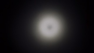
Original Light beam from stock lamp from Body 2
7 Leds - Claimed to be XML2 T6 but doubt so. Measured wattage draw on 13.3V battery was 0.7A, would be driving the each individual LEDs at about 0.3A? 1W per LED

ISO 100, f1.7, 1/16000, 3 feet
Body 2, 20mm 8 degree reflectors
3x XHP50 @ 36V 1.35A
https://www.youtube.com/watch?v=-A2LZJfspqg A short video of my main switch with a light indicator to show that the lights are on. It pulses in respect to how bright the main lights are depending on the potentiometer setting.
Some build photos


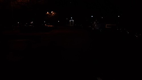
Beam shots
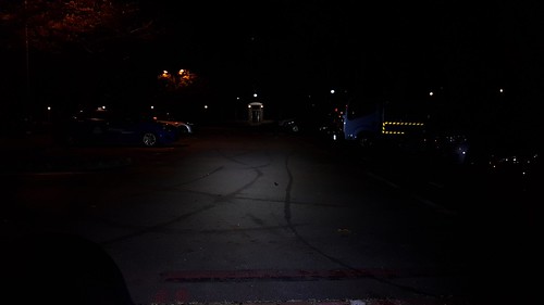
Shot @ ISO 100, f1.7, 1/45s
ISO 100, f1.7, 1/45
Bike's headlight on
ISO 100, f1.7, 1/45
Body 1 @ Full, stock reflectors
3x XHP50 18V 2.75A

ISO 100, f1.7, 1/45
Body 2, 20mm 8 degree reflectors
3x XHP50 @ 36V 1.35A