How much light could a flashlight flash if a flashlight could flash light?
A square body ?
Now that’s innovative !
![]()
I don't think it's going to be square.
Looks like a rounded triangle:
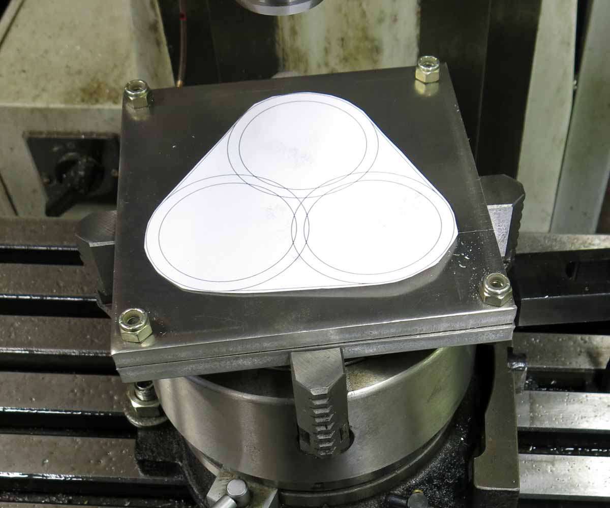
Yes it will end up being some sort of triangular shape. The material is square as a factory I visit guillotined them for me from scrap.
Nice start. 10mm aluminium, a plan with bolts all over, you have my approval! ![]()
Looking good already! I’m glad you joined. Your builds are always amazing!
This will be cool :+1:
Starting off pretty well MRsDNF! I hope to return in a few months to see the outcome ;)
Six 2.5mm holes were drilled through the bezel. This will allow cap screws to pass through this piece and thread into the base to hold the lenses and o’rings captive.

The outside shape of the bezel was then roughed out with a 1/4’’ end mill.
And then the corners were started.
Pretty much everything machined on the bezel is worked out on a pitch circle diameter. The PCD is inputted into the digital readout along with how many holes you need on the PCD and a start and finish angle. The digital readout then tells you where to wind the X and Y axises to for your holes.
For example the corner in the above picture had a PCD of 72mm with a starting angle of 300 degrees and finishing angle of 60 degrees with a total amount of 30 holes for each corner.
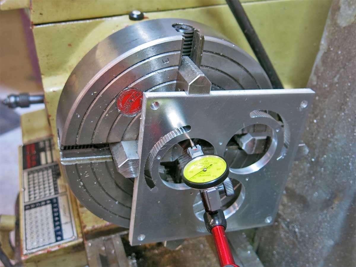
This picture shows the position where hole 17 is, X and Y reading zero.
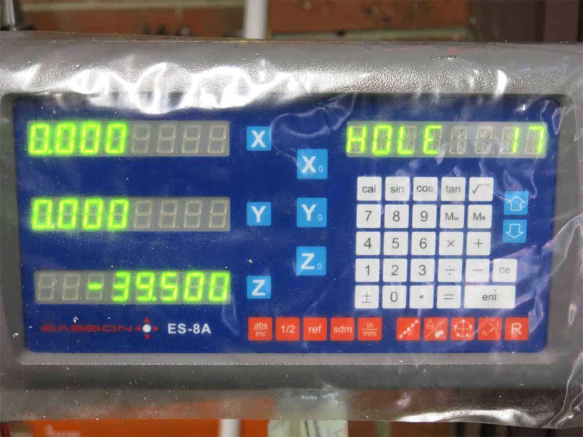
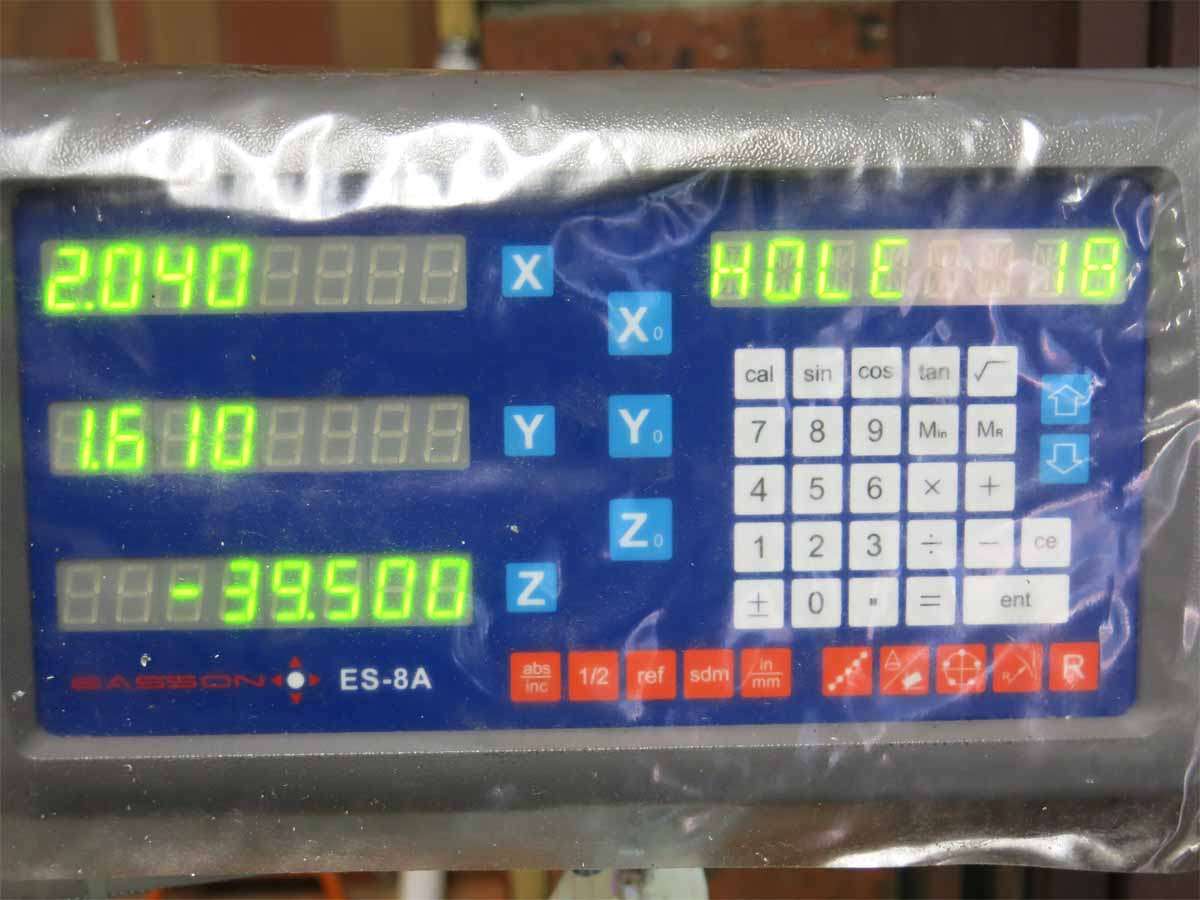
This picture is showing in mm where the X and Y is for hole 18.
X, 2.04mm is the table moving length wise and Y, 1.61mm is the table moving in and out.
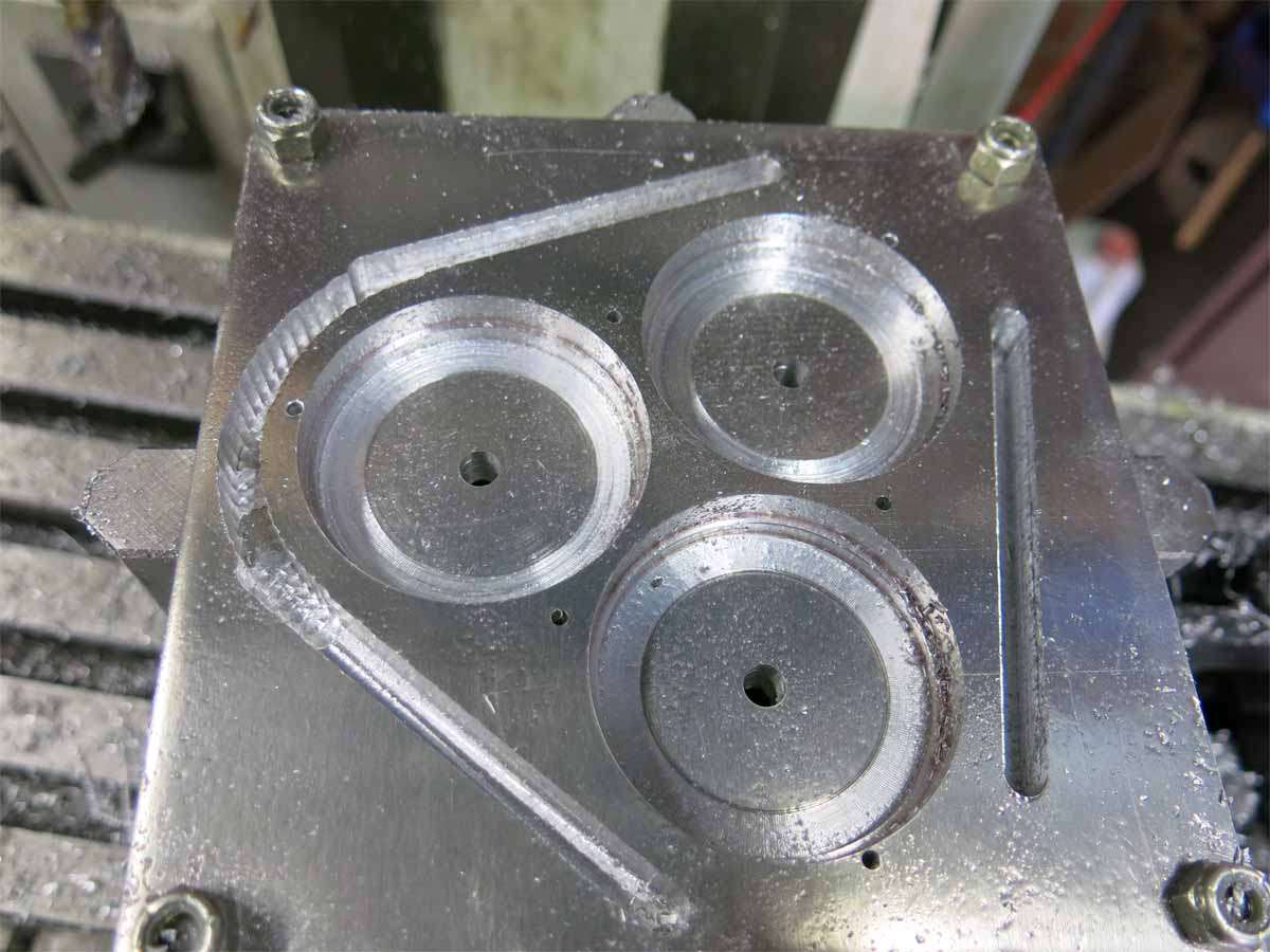
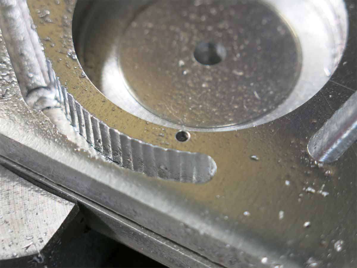
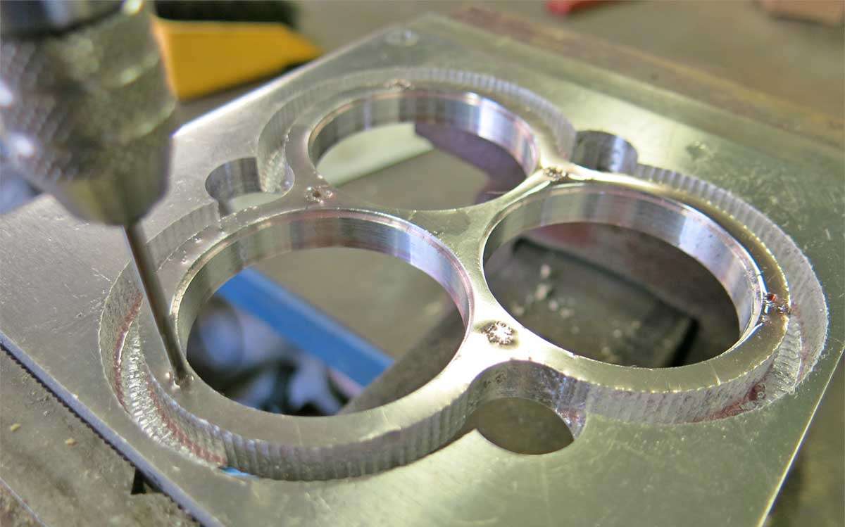
This is with 17 holes machined. The corner is taking shape here.
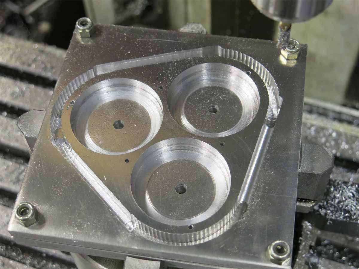
And the finished bezel. The corners will be cleaned up with a file later on.
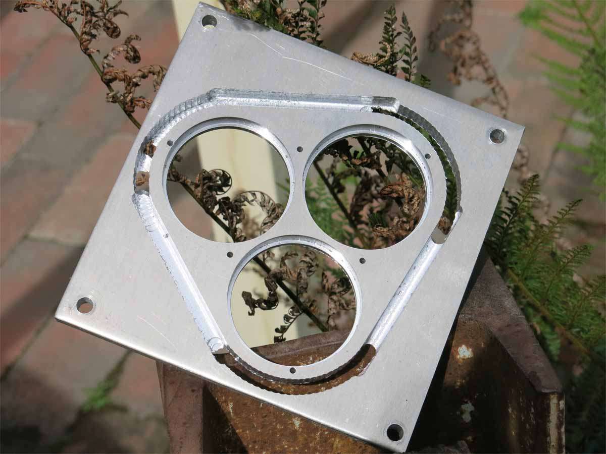
The bezel removed from the mill shows the corners where I have milled through and the straight edges have .5mm left holding it together.
And then we start again to machine the base of the bezel. This will be threaded m2.5 in the six holes.
Having just seen the artistry and skill level (very high) of two of your masterpieces, this one is bending my mind with anticipation,
or constipation not sure which 
Cheers David
Thanks pommie. It was a pleasure meeting your good self and daughter yesterday. Its always interesting checking what another flashaholic keeps in his pantry. ![]()
Just got around to viewing the update on the PC screen. Bezel is taking shape nicely.
That’s just way too much work man… For those that might not know just to do one of those corners Mr. Steve has to move his x and y axis on his milling machine and make a cut ~ 35 times for each corner. What make and model is that DRO you’re using? Our old Mitutoyo XY at the shop just died recently.
Thanks FMC. The retainer will be a lot more work when I get to it.
Yes, lots of cuts Turningbluechips. The DRO is an Easson ES-8A. I doubt it would be the quality of the Mitutoyo as its what came with my Chinese Mill.
lostheplot just bought a cheap DRO on Ebay and put it on his mill. Haven’t heard any reports on it yet.
excellent Steve
btw its hip to be square
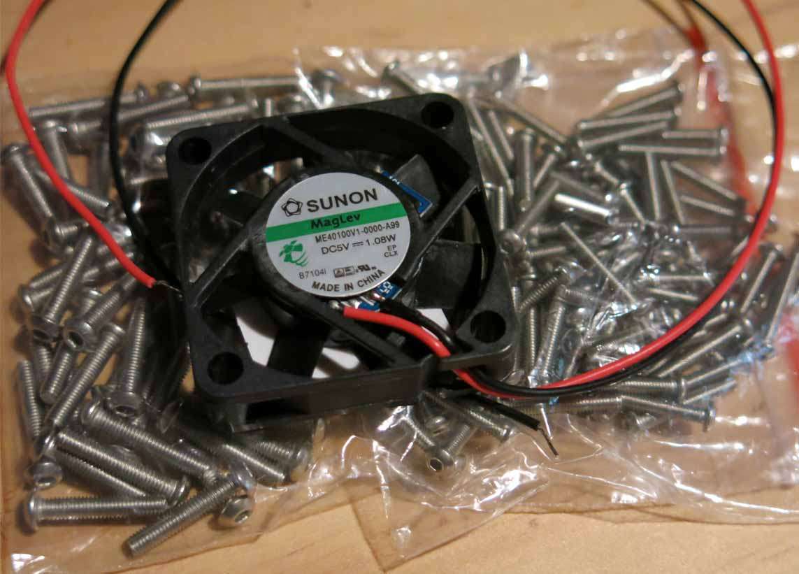
Being away last weekend nothing got touched on this build. I did receive some 2.5mm and 3mm button head cap screws and a fan which hopefully will somehow work its way into the torch for cooling.
Active cooling, eh? Is that for the torch, or is it getting hot down there already?? :sunglasses:
Its for the torch. Its dam cold down here and its not warming up anytime soon. :weary:
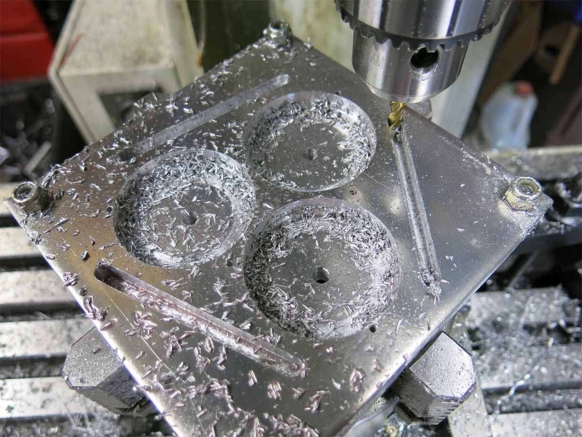
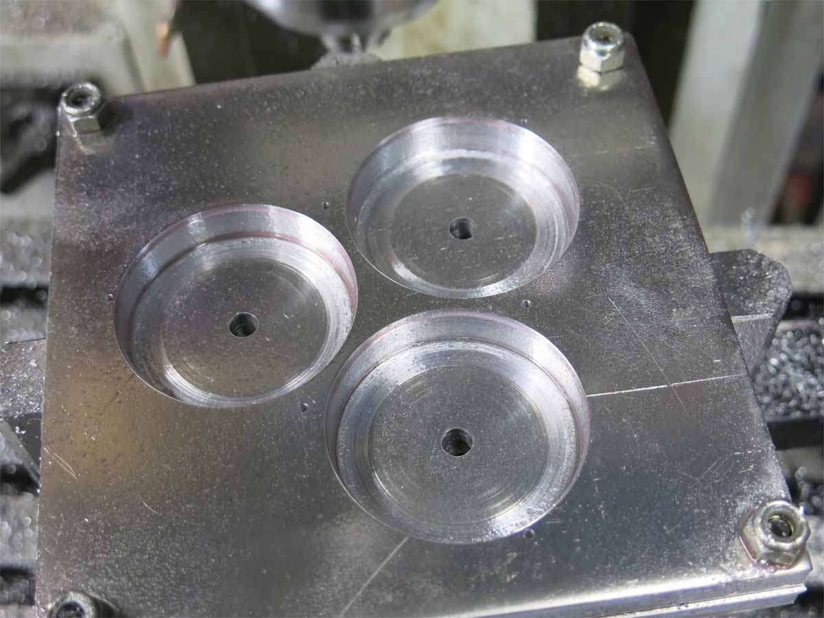
The process pretty much follows the same theme with the bezel retainer as it did with the bezel. Machining started of with three x 3/4’’ holes.
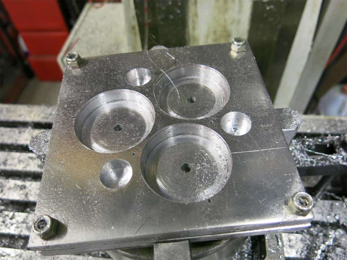
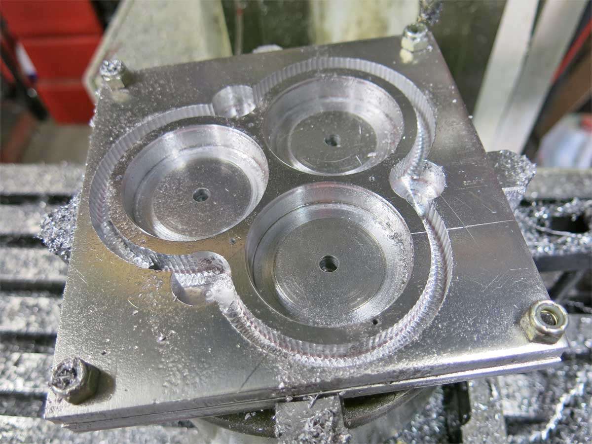
This was followed by plunge cutting 180 holes to end up with this shape.
Tapping the six holes in the retainer was the most nerve racking part of the build so far with my reputation of snapping of small taps. These holes are tapped 2.5mm.
The bezel was then set up in the lathe held in the four jaw independent chuck so the reflector openings in the bezel could be tapered slightly. Of cause the bezel had to be positioned three times to do this.
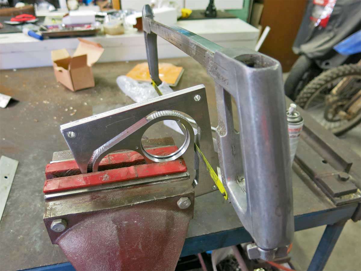
The hacksaw was then put to use to cut through the remaining aluminium in the slot to give us the rough final shape of both pieces.
With the help of a file and lots of chalk the parts started to take on their final form. The chalk in the file teeth helps stop the file clagging up with metal filings and scoring the filed surface.
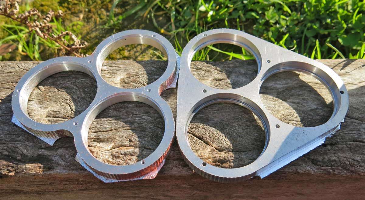
And here is the bezel and retainer after lots of filing and sanding. These are not polished or debured at this stage. I’ll do that later when the lights closer to completion as I’m sure I’ll get some scratching on them before its finished.
And finally the two parts bolted together.
Its now back to the drawing board to work out how to proceed next. :person_facepalming:
![]() :+1:
:+1: