I’m not home to check at the moment but I have both of those lights. I’ll check this afternoon and let you know.
Yes, Thank you.
Yes, looks to me like a part that fits the A6 would fit the EE X6 as well. That would be a very nice part to have available.
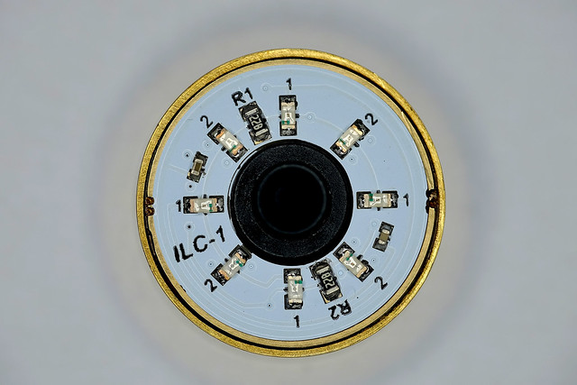
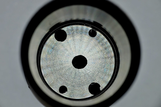
Also I have a question. I’ve been poking at my lighted tailcap module ![]() I pulled off the LEDs of one channel and swapped them for another color, trying to achieve a two-color alternating look. Now I have a strange behavior. When I first put power to the tailcap, the original white channel flashes quickly then goes back out while my new orange channel stays on all the time. What would cause that? Is there a fix?
I pulled off the LEDs of one channel and swapped them for another color, trying to achieve a two-color alternating look. Now I have a strange behavior. When I first put power to the tailcap, the original white channel flashes quickly then goes back out while my new orange channel stays on all the time. What would cause that? Is there a fix?
Could you check tailcap current? Which resistor values you put on each channel? Also please check voltage across each resistor, it should be 0.1V. No blinks should occur.
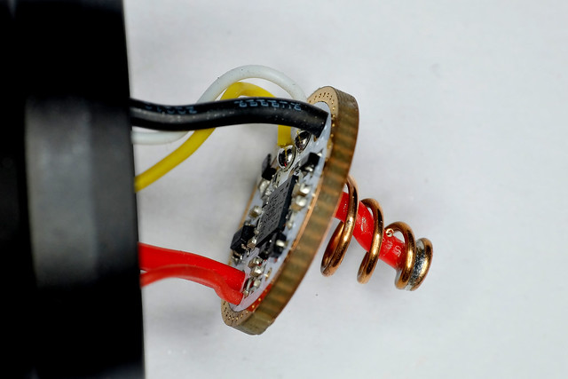
There are some components on bottom(inner) side of top PCB, and they are soldered with lower temp lead free solder (~145C), top side is soldered with normal lead free solder (~217C).
There is a possibility of de-soldering components on bottom side if you use hot air on top side,but if ILC-1 is still, those components would remain in place because of solder cohesion force. For resistor change better is to use normal iron, not just because of bottom side components, but because of Omten switch which is close to resistors and it's made of plastic that doesn't like temperatures >120C.
I did it by hand with an iron. I learned my lesson about pointing hot air at black plastic switches a couple of years ago, but that’s a different story ![]()
I stripped the #1 channel completely and built it back using 4 orange LEDs and a 33 ohm resistor. That was just a guess based on the fact that these things are a lot dimmer than the white ones you had on there, but to be honest they’re still really dim and I’d like to lower that value even more if its possible. The #2 channel still has the white ones, but I did raise its resistor to a 330 ohm since they’re brighter than I wanted. I tested it with the original (was it 89 ohm) resistor in place first and when it flashed off I thought I’d lower the draw a bit and re-test since the white was too bright to start with. No change, it behaves the same with both values in the circuit. I never measured the draw before the resistor change, but right now its 3.34 mA @ 4v.
One development: it only does the flashy thing with the driver in the circuit. If I bypass the driver or use my bench power supply both channels work as intended. 3.34 mA sounds like a lot since your specs say up to 600 uA. Is it too much? Are my orange LEDs just too inefficient?
EDIT: Just because I can’t leave things alone, I pulled the resistor off of channel 1 and just left it open to test. Obviously only channel 2 works, so only the 4 white LEDs are powered, but tailcap current dropped to 300 uA and no more flashing problems. So I guess I’ve answered my own question — too much current draw the way I had it set up. But I’d still love to hear why it does that, just for my own curiosity.
33Ohm resistor? That is to low, total current will be too high.
You have equation in datasheet, and also under specifications "Max. recommended current: 600uA total (channel1 + channel2)"
Current can be actually up to ~1mA by design (that would be something like "absolute maximum rating"), but I'm always conservative about max. spec and I always leave some safety margin for reliability reasons.
Over that current weird things can occur.
Original resistor definitely wasn't 89Ohm,it was ~825 Ohm.
If you want orange-white combo, and since orange is something like 5 times dimmer, set orange channel 500uA (200Ohm - resistor set doesn't contain resistors lower than 330Ohm,but you can stack two 412Ohm), and try adjust white first to 100uA (1Kohm). For this adjustment a multiturn potentiometer temporally connected to channel would be best to find out best current/resistance.
Yeah its very possible that I misread the numbers on the original resistors. Those things are tiny! ![]()
Thanks for the advice on the resistor values. I’ll sit down this evening and give those a try. I really appreciate your help.
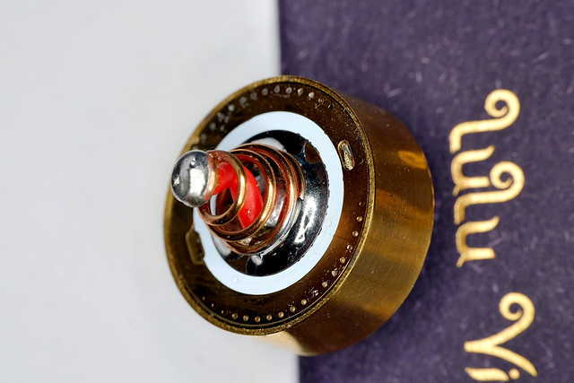
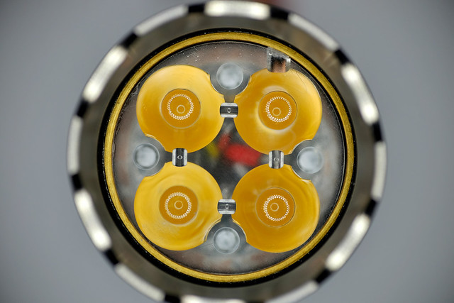
So after much experimentation I decided that my orange 0603 LEDs just aren’t going to work in here. Mine are just too inefficient. Just driving them to a reasonable level by themselves passes that 1 mA line. Maybe I can source some better ones, I don’t know. So instead I pulled those back out and dropped some red ones on the board. And it works! I wound up with 1kOhm on the white channel and 165 ohms (2x330 stacked) on the red channel, for a combined tailcap draw of ~710 uA.
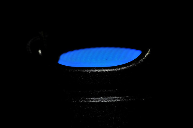
Not the best picture but maybe you get the idea:

Thanks again to Neven for all your help. I’ll definitely be ordering more of these parts in the next few days. Hopefully you can get single-emitter mosled boards up and eventually smaller tailcaps for the A6/X6 sized lights as well.
Actually strike what I said above, I’ve already changed it. Too pink for me, on this orange host. Its now a red channel at 230 ohm (330 + 750) and a yellow channel at 200 ohms (330 + 510), with a combined tailcap draw of 940 uA. I like this a lot better, since the red and yellow kinda “blend” to make an nice orange-ish color.


I really like this tailcap. The 4x2 looks great I think (although I really like the 3x2 too) and the LVP option just pushes it over the top. I’ve killed cells in my rarely-used lights with the “normal” lighted tailcaps, completely dead and sent off to recycling. ![]() No worries with this one, and I love that.
No worries with this one, and I love that.
Awesome mod there for the ILC stuff, emarkd!
Wish someday I can order this piece and Neven can do the dual color, too. LOL.
Waiting for the multi voltage version of this new LD4 driver.
Very nice look there! I’m glad it worked out for you!
Oh THIS would be perfect for my MokeGane Sinner 18350! Horrible time to have the checkbook so low… (scrambling)
Just ordered a couple of drivers and a couple of mcpcb’s from the site, looking forward to seeing this in action… will probably have questions ![]()
Edit: Cool! I like numbers, seem to always be tying numbers to events and such in my mind. I was born in ’62 and here I am posting about my first led4power purchase in thread post #62! AND, today is my parents 66th wedding anniversary. ![]()
FWIW (and to help me remember) I purchased both drivers in LD4-B trim, one set for 12A to go with the Quad board loaded with Nichia 219C emitters for my (next) Emisar D4. The other set to 6A for my MokumeGane Sinner with the Triple board loaded with XP-G2 S2 2B emitters. (or that’s the plan, going in)
Awesome, sounds like some great setups. I ordered 3 more drivers myself, and some of the single-emitter boards. Really looking forward to what you do with the Mokume Sinner. That light is easily one of my favorites anywhere. If it ever needs re-homing…. ![]()
Small parcel has been received, thank you!
![]()
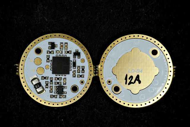
Convoy M2、LD-B4(12A)

LED:Nichia 219B V1 R9080 4500K
120uA

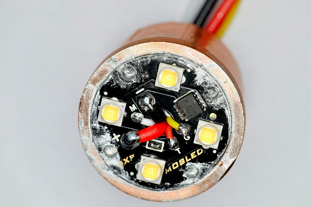


Pictures and build quality are both impressive
I'm considering to add customer's product gallery on my web page (also coupons as reward for taking these pictures).
WoW, That’s great.
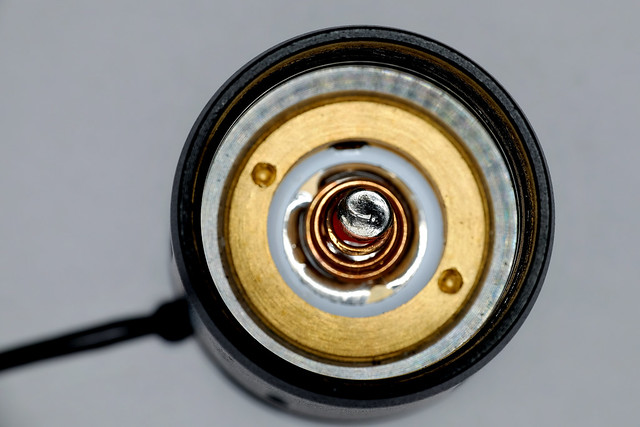
![]()
ILC-1 illuminated tailcap, 120uA
How to change to 80uA?
80uA > this is 40uA per channel, equation from datasheet: Ich=100/Rx, or Rx=100/Ich=100/0.04=2500Ohm, so change both resistors to 2,5kOhm. Be careful with heat close to OMTEN switch (low temp. plastic).