Hello,
I have been conversing with (cpf) techjunkie about the ever popular method of using multiple 7135 circuit boards as Master/Slaves in order to use multiple LEDs without having to go the series routine and have to use high voltage.
The following is a copy of the PMs between me and techjunkie. It's rather long and I hope it's clear enough as there is a lot of "quoting" in it, so read through and see if it helps. I did highlight all his replies in red.
1. Re: Everyman's Mod
Originally Posted by Old-Lumens
Hello,
I've seen some of your mods and they are fantastic. I do some modding too (mainly at BLF), but I am illiterate when it comes to electronics circuitry. I have questions and I just can't seem to "get it" when reading posts in the forums, about this circuit (Everymans)...
Justin,
The easiest way to explain it in layman's terms is to think of it as three flashlights in parallel, each with their own regulators, but all powered by the same set of batteries. Much like anything you plug into an outlet in your house runs in parallel to everything else in your house. Your TV, lamps and refrigerator all draw different amounts of current without changing the amount of power run through the other devices because individually, they are self regulated. The same thing is happening in the flashlight.
Each of the three regulators in my Everyman's Build is controlled by a single mode board that just happens to be on one of the regulators. The way that the mode board controls the three regulators at the same time is less like a light switch or dimmer switch that could control several chandeliers in your house at once, and more like a single remote control that would change the volume on three of the same TVs or stereos at once.
Originally Posted by Old-Lumens
I see how you have used the 3 XM-L emitters in parallel, but that's not really in parallel? because of the three boards? I still don't get it, since they still all have the same power lead aren't they still in parallel? If the boards are regulating, how does that control the voltage, since the boards are linear and only control amperage.
Also one board is the master and the others slave. Isn't that more of a load on the master than it is recommended? I mean, will it cause the board to burn out faster, with the extra draw pumping through it? If the amps are being drawn out of the master board isn't that three times it's limit feeding the other boards?
The way it's wired, 1 board + 1 LED makes 1 circuit. The three circuits are wired in parallel with each other. Each (sub)circuit is regulated by its own board. The regulation of those three individual sub circuits is controlled by a single mode board. Don't let the fact that the mode board is installed on one of the regulator boards confuse you. Technically, it's a fourth sub circuit that runs in parallel to the other three regulator+LED circuits.
Each regulator controls amperage by modifying the amount of resistance it applies to its individual circuit, which in turn selectively lowers the amount of voltage left to the rest of its circuit (the LED) to have the effect of regulating the amperage of its circuit. Less volts to the LED = less current drawn by the LED = less amperage.
Originally Posted by Old-Lumens
There are loads of multiple emitter mods I would like to do, but I will not use Li-ion and NiMHs are limiting due to the room needed to do series emitters. I would love to do the parallel thing, but is it as safe for the emitters as series is?
What is the limit of this circuit? 3-4-5-6 emitters? How many can be done together that way?
Because each regulator is individually controlling the current applied to each LED, it is just as safe as a series string. At the crux of it, that's the point of the design. There's practically no limit to the number of emitters that can be connected this way, but the obstacles are voltage sag of the batteries as the total current (amperage) drawn from them adds up, and also the limitations of the switch. The Mag switch is OK for up to ~10 Amps (I'm about to push it to 12A with a 4x version of the Everyman using 3.0A regulators instead of 2.8A regulators). Beyond that, you'd be best to have the switch only control a FET switch capable of higher loads.
Originally Posted by Old-Lumens
I would appreciate it if you could take the time to try to explain to me how your circuit works and how it remains safe and controlled in a simple way that an electronically challenged person might understand.
I know you must be very busy, so if you don't have time for my questions, I will understand.
Thanks in advance for your time,
Justin
My pleasure.
Thank you very much for the explanations.
A couple more questions about your drawing. It seems that not only the 8 pin controller has to be removed on each slave, but also the resistors at R1 & R2, is that correct? Also in your drawing I see what looks like a resistor crossing two pin sockets (where the controller was). Was that something you did and why?
Thank you very much. I would like to try to duplicate this mod, as there are a number of people asking on BLF, but not getting answers.
Also may I "quote" part of your replies at BLF, if I post a description of how the driver setup works?
Thank you once again,
Justin
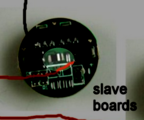
Those are photos of KD sku S004338, which is the single mode version of the board. I think they bridge the two contacts where the 8 pin controller was just to connect the power input from the spring to the VDD inputs of the AMC7135 chips to power them. There also appears to be a 0ohm sense resistor near the LED+ contact that might also serve to bridge the Vin to the LED+. Neither was necessary the way I did it, because I already had excess multimode chips and simply opted to remove everything except the AMC7135s and wire Vbatt directly to the LEDs and the VDD out signal from the controller directly to a trace route connected in parallel to all the VDD contacts on the 8x7135 chips on each of the other two boards.
Go ahead and feel free to pass this info on to BLF. Just be careful not to misquote me and make me indirectly responsible for misinformation.
EDIT: 04/06/2011 - Added corrected photos and new information, copied from TJ in Post #38
Just saw this thread and want to point out that in both Old-Lumens drawing and my original drawing above, there's one important thing missing... the ground wires that connect the slave boards to ground. Without those, LEDs 2 and 3 won't light. Here's the modified drawing:

Even better, here's a mod to the method above, whereby only the low current required to operate the micro controller goes through the switch, but not the high current for the LEDs. In this method, the regulators are operated by the mcu like a low current switch can be used to operate a FET or a solenoid switch. By doing this, the switch resistance is eliminated, thereby reducing parasitic resistance and increasing regulated runtime:

You can use any number of regulators and LEDs. The pic above shows 4-4, but 2-2 or 3-3 or even 5-5, 6-6, etc. would work the same way. Note that bypassing the switch to eliminate resistance is great for 3 cells or 4 weak cells, but I actually had to improve regulator heatsinking and add resistance back in when using 4 powerful cells and 4 tightly stacked regulators to avoid them overheating and throttling back.
------------------------------ END OF COPY --------------------------
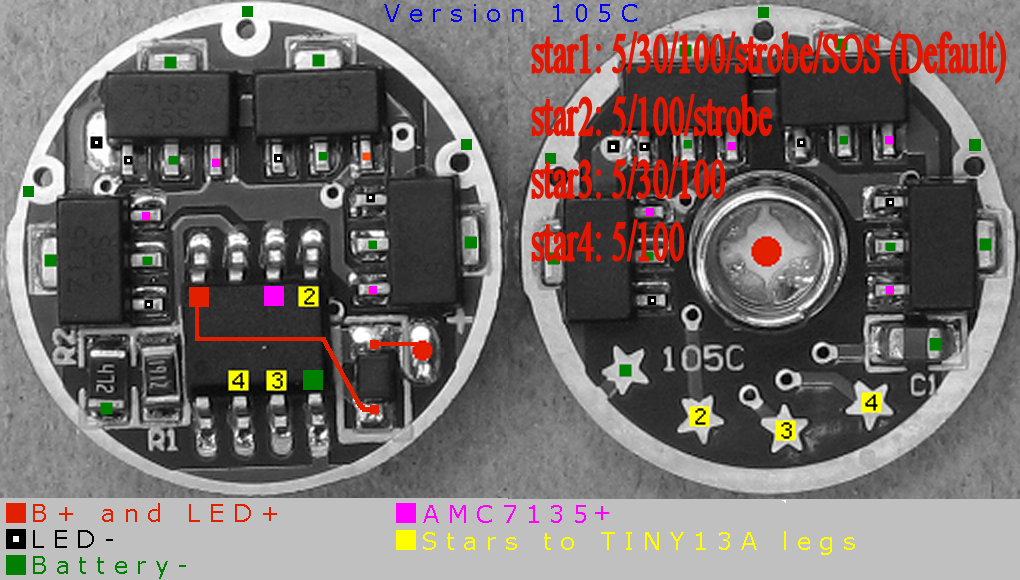
Also, here is a photo showing which star to bridge for different modes. This only works on the board shown, as I know there are several variants floating around.
Hopefully this will answer some questions for people. It did for me.
Thanks to techjunkie for taking the time to answer the questions and do it in such a direct manner.
Justin