I'm surprised to hear there was glue there. Maybe I missed it on mine or wasn't there - was it clear in color? Might explain to me why one of my light's battery tube did worse than the others.
Something was there on all 4 screws. May have been clear originally. Pretty certain it wasn’t Loctite (didn’t turn to white powder and wasn’t real hard) so I just called it glue. M2.5 tap cleaned the glue and anodize up.
2 M3 screws on the driver were clean, dry, not glued.
Hello as i write before i recieved today my q8, but unfurtunatelly have the led button problem.
Im trying to help with some photos. My idea was open the button holder ,show some photos, and later fix the led when fix is oficially anounced.
Of course im not modder,or something similar a i have 0 knowleges about this things but i want my q8 full as expected.
To do that i need to remove the button holder i dont know how to do this. Im trying with some tools but, im only doing scratches etc
What tool do you use to do this? Can you do a little how to with 1 or 2 photos please?
Thanks in advance, sorry for me english hope you understand.
If I have time, I'll try to take photos tonight. I used a pair of needlenose with rounded backsides (near the tips, not the pinched surface but outer surface). Using these, insert in a pair of notches in the switch retaining ring (there are 3 1/2 circle notches in the ring), gently apply CCW pressure, while keeping outward pressure on the ring.
What should help preventing scratches is adding some masking tape on the tips of the needlenose.
I've often wondered if a proper tool existed for doing this. Ideally it should be a hard plastic of some sort, rounded outer edge to fit the 1/2 circle notches. I'm sure I could make one out of plexiglas, or something equal, but would probably take me hours.
A machinist could probably make a jig for this in minutes.
Thanks! I will try tonight that tonight, i think with the info you give me gonna be more easy!!
Very apreciated
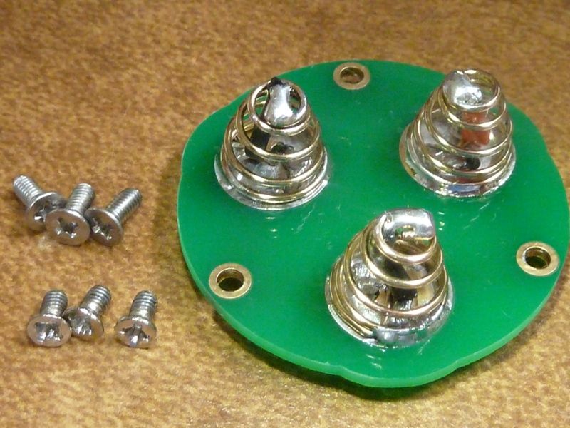
Just rebuilt the side SW pad. Used lower brightness White 0805 LEDs and a 223 or 22Kohm resistor also 0805 size.
LEDs were more white before install, guess its the silicone button made them look like Cold white, bluish.
Top 2 pics are brighter lighting than the bottom 2 to give an idea what it is. Perfect IMO, enough to find the light SW indoors or darker, and not be annoyingly bright on the night stand.


Did you ask Miller to ask ThorFire what tool to use?
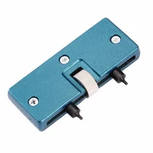
There’s a tool for removing bezels from watches, widely available.
A handle with 2 pins, one in an adjustment slot for separation.
Yeah!!! Received mine today. Initial thoughts are :+1: Switch led’s appear to be equal (maybe a bit too bright), and no issues so far with them getting flaky. Love the ramping, and wow, this thing is bright. Had to dig through the manual (got a little click happy, and induced lockout). I thought I broke it.
Very well built, as I knew it would be. Can’t wait for evening to compare it to a few of my other lights.
Thanks to Thorfire, and the great Q8 team for making it happen.
cool!
Only issue there is watches are usually SS, some titanium. This is anodized or coated aluminum, subject to scratching much easier.
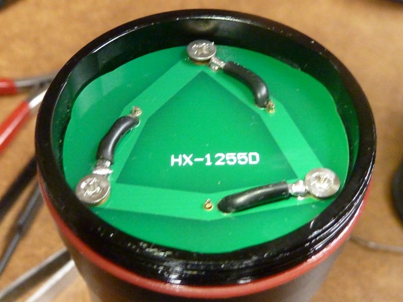
I like to do the same sort of thing, but rather than just beefing up the traces with a thick layer of solder (not really a great conductor), also embed a piece of solid copper wire in the solder (e.g. stripped from 1.5 mm^2 or heavier “twin and earth” household wiring, a UK standard). And where possible plug the current-carrying vias with solid copper wire, soldered both sides of the PCB.
Desoldering braid is also good for bypassing springs, when insulated wire is not needed, as in this case. Very neat when you can also fit it inside the springs. I also try to solder the inner and outer springs together at the pointy end, to mitigate any poor contact between them, maybe developing over time.
I made this jig up from plexiglas for a front bezel, cut to size then molded with a rotary tool. Something similar could be done for switches:
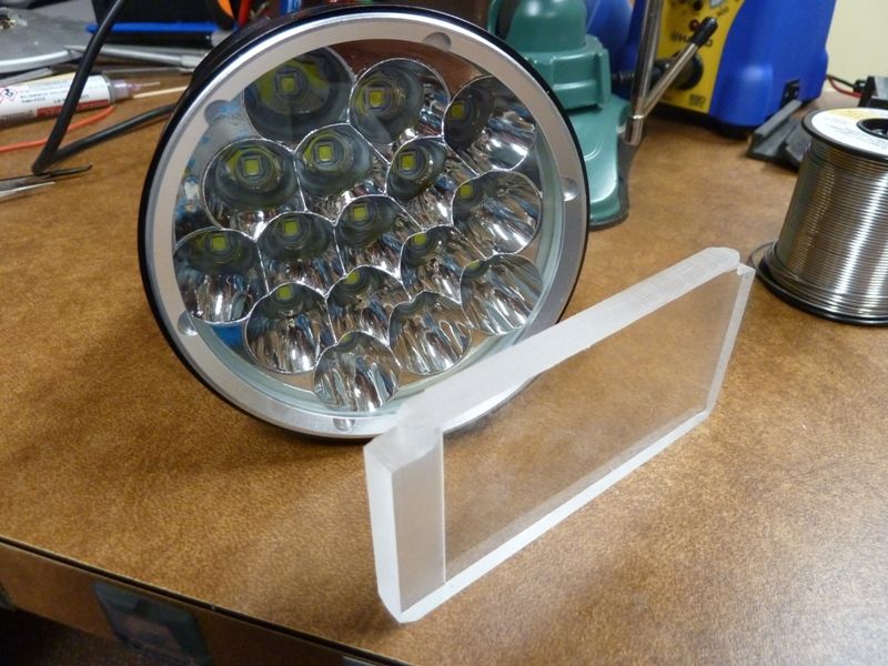
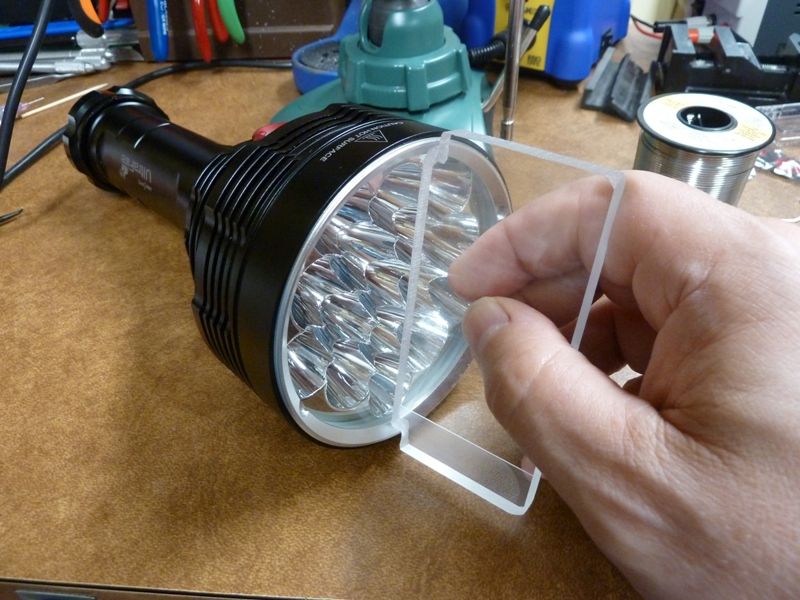
I did this for the 16X XHP50 light shown above:
Replaced stripped stock screws as well. At 37K lumens with 2S3P, there's lots of amps going thru this.
So until i get my hands on a XM size ledboard my Q8 is nearly ready.
- 20AWG Spring bypass + thickening the traces and installing a 16AWG loop for measuring the Amps.
- 16AWG ledboard wires
- 2,2k switchled resistor + 2x0603 UV LEDs´s
whats left is changing the srews when they arrive.
Sorry for the shaky pictures (new meds have sideeffects)


What is this light?
The bare 22AWG fits into the via (hole) in the center of the spring pad and gets better contact to the traces on both sides of the PCB. Desoldering wick may not be the way to go on This Lights design.
Best is what Tom E did above. Drilling the hole larger to use a wire as close as possible to the screw contact hole and the traces on that PCB he modded there is anemic compared to the Q8 board. My wire was long enough to lay into the soldered traces and follow to a screw hole. But I didn’t feel it would make enough of a difference with stock driver and emitters.
Here at FT: https://www.fasttech.com/products/4173002
$60 w/BLF discount. Big moddable light but typical budget clone stuff all the way. It's far from ideal. I had a custom alum plate/heatsink made for it, but could not permanently mount it because only way to access the driver is from the top (reflector) side. Inherent modder design flaw, but I used thermal grease to do the best I could with it. SRK size drivers fit perfect.
What I really, really like is the 2S3P battery configuration. 2S4P is little too big to hold comfortably (GT) and 2S of 26650's is not enough power.
OK, thanks. Perspective doesn’t give this battery tube justice, it really looks smaller. ![]()
Pro Tool to open camera lenses
I don’t know if these thing is small enough for the switch ring
https://www.amazon.com/Neewer-Professional-Stainless-Spanner-Opening/dp/B00J5F6ZI2
Ohh, some update on this. ThorFire told us the contaminant in the screw holes for the tail PCB mounting is sand blasting remnants. This is consistent in what I've found as well - fine particles, but not metal.
Also fyi, I actually got in 9 pieces total of Q8's. 3 picked up Saturday at the post office, 1 came Tuesday (Expedited via DHL), and 5 were delivered yesterday (USPS). I felt a little bad bout gobbling up 9 in the first 500, but 7 are spoken for, leaving hoping to keep 2. I thought this would be a nice sample size to look at production/QC issues as well, all together, all in one batch.
So good news:
- All are in great shape - no scratches, dings, fingerprints, mis-aligned LED's (except for what's known...)
- All units work, all units have working SW LED's. Of the 9, two have noticeable brightness differences
- the heads seem consistent: drivers and LED's - great consistent tint unit to unit, seems to be equal performance (not all tested yet)
- most lights came with threads pre-lubed. One or two lights were either close to bone dry or were bone dry. I'm gonna Nyogel them all!
Not so good:
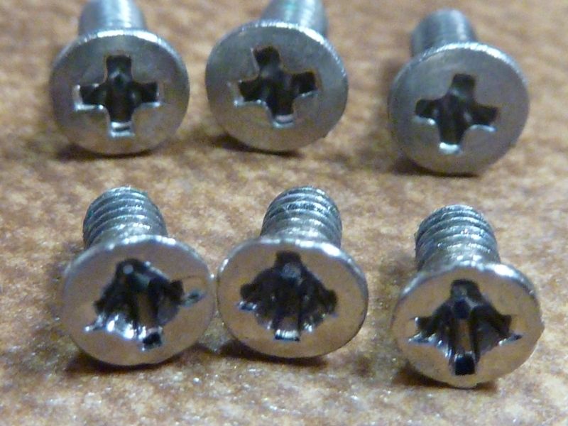
- some of them have stripped out screw heads, but can be loosened, just not re-used easily. One light had all 4 screw heads on the tail PCB stripped
- some inconsistent lumens output measurements, one had a noticeable mild flicker - could not see it but could measure it - weird
- swapping parts and such, seems like the lower performing units have lower performing tail/battery tubes - suspect the screw contact to the tube, which really corroborates vwpieces findings. I've seen case of best to worse at like 12%. Also seems like harder tightening can bump up a low reading, but over tightening the tube to the head results in higher wear on the driver ground ring, where the tube contacts it. There is very little surface area of contact being made - you can see the contact marks after a couple/few times of loosening/tightening. We were concerned about this, but I don't see evidence they attempted to beef up that ground ring - not sure if they were going to do anything or not. A brass retaining ring would have done the job better, I believe.