Looks like we got the same results! Awesome.
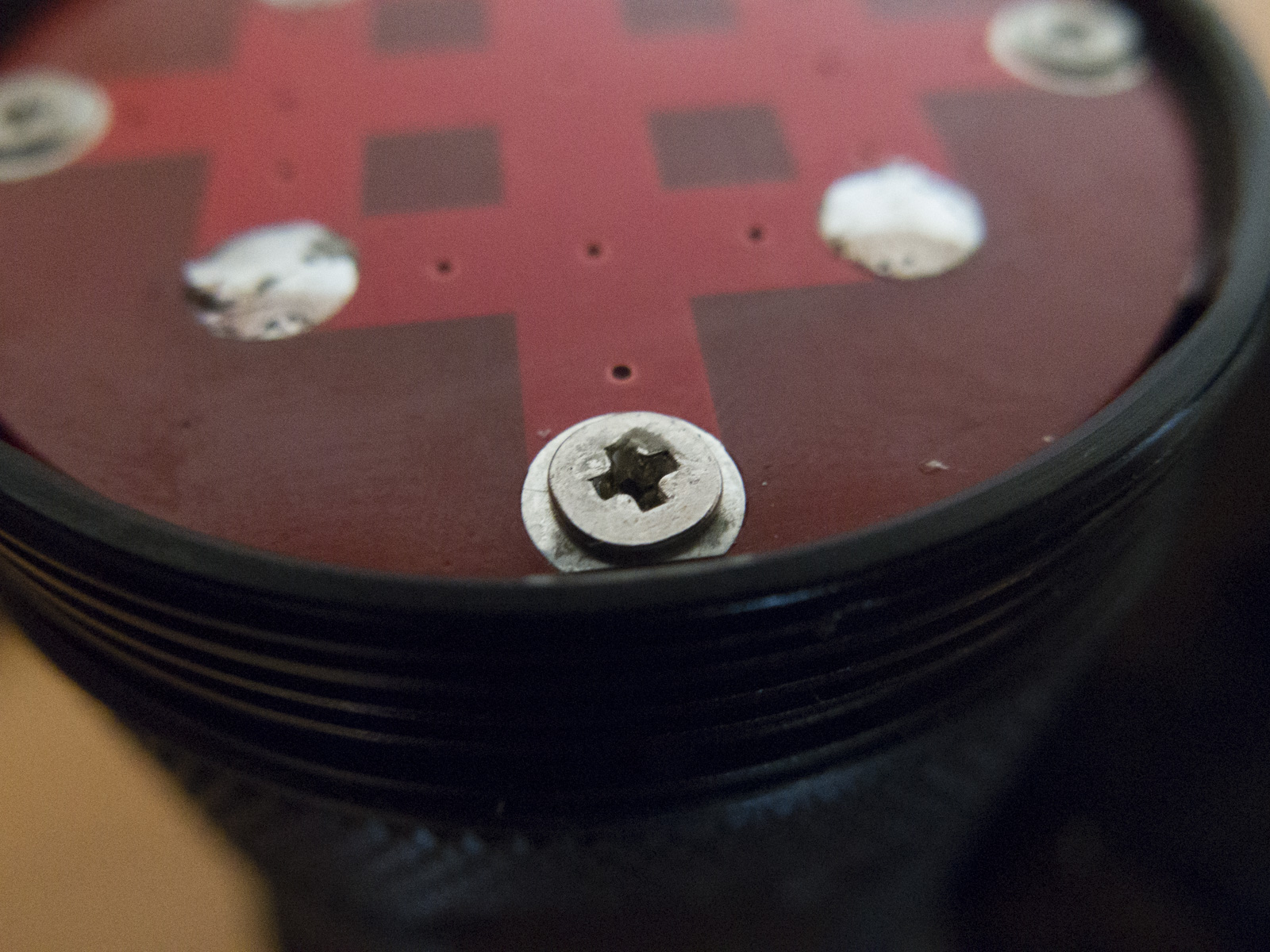
Has anyone actually removed the reflector screw? Mine has to be superglued or something…
Things I might try:
Penetrating oil and whack a small cold chisel into the head to try to make a slot for purchase.
Penetrating oil and try to turn the screw by tapping the head around using a punch or cold chisel.
Drill or grind the head off, once it’s apart try to unscrew the stub with pliers, mole grip etc.
Drill the screw out all the way down, if you are really good, and lucky, you just might keep the threads in the reflector, otherwise be prepared to tap it the next size larger, or helicoil it.
Ask a favour of a colleague to EDM (spark erode) it out (you probably need to work in aerospace for this option).
Tig or stick weld something onto the head that you can crank on.
Edit: if there was any sort of head left un-mullered, I’d first try an impact driver, with a diamond coated bit.
Thanks for all the tips guys, but I think I’ll give up for the time being.
I quite satisfied anyway. I just hoped that I could change the LEDs to 219c 4000k.
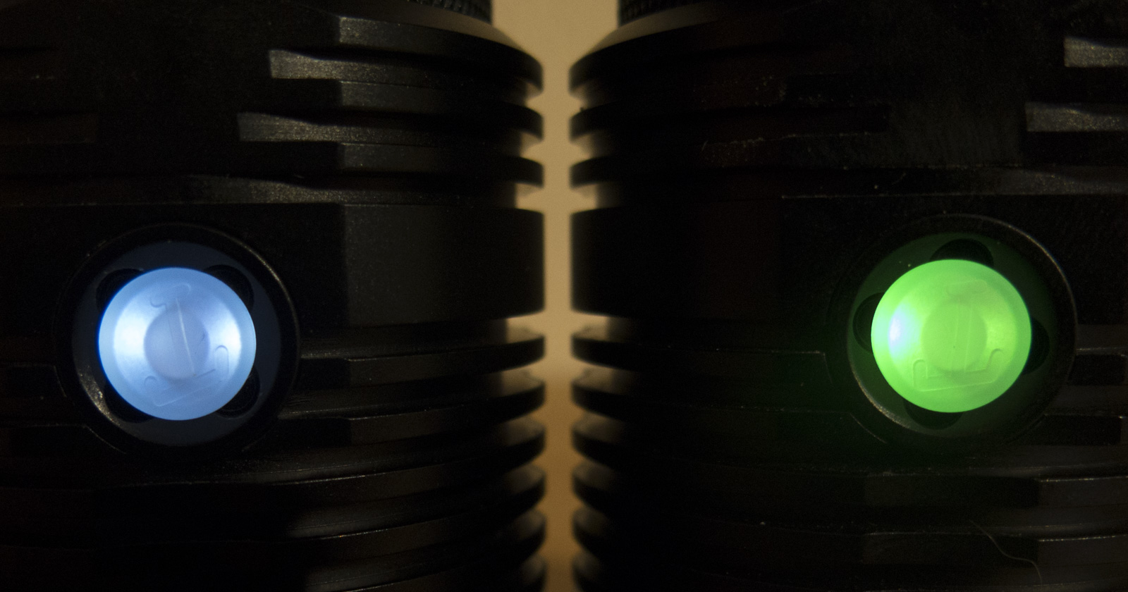
I measured the candela to 56kcd when I first got it. Now after spring bypasses and drilling bigger holes in the driver board I got 73kcd ![]()
side switch board modified to even out the LED brightness
Cree LEDs of the same reel usually have quite the same Vf,
but for those tiny SMD LEDs the emitting area is a lot smaller, so they may vary a lot more
Unsoldered LEDs and switch just holding my temp stabilized iron at 300°C at the other side
also skillet might work well
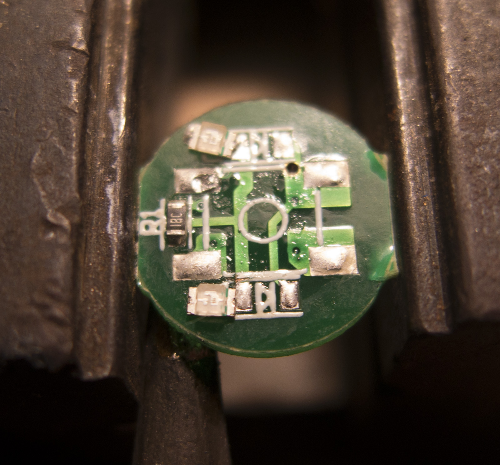
then cut the trace to one LED and add a resistor
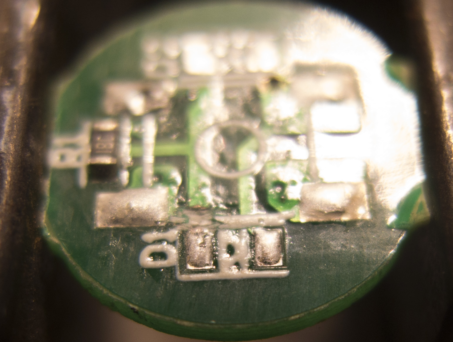
add solder paste
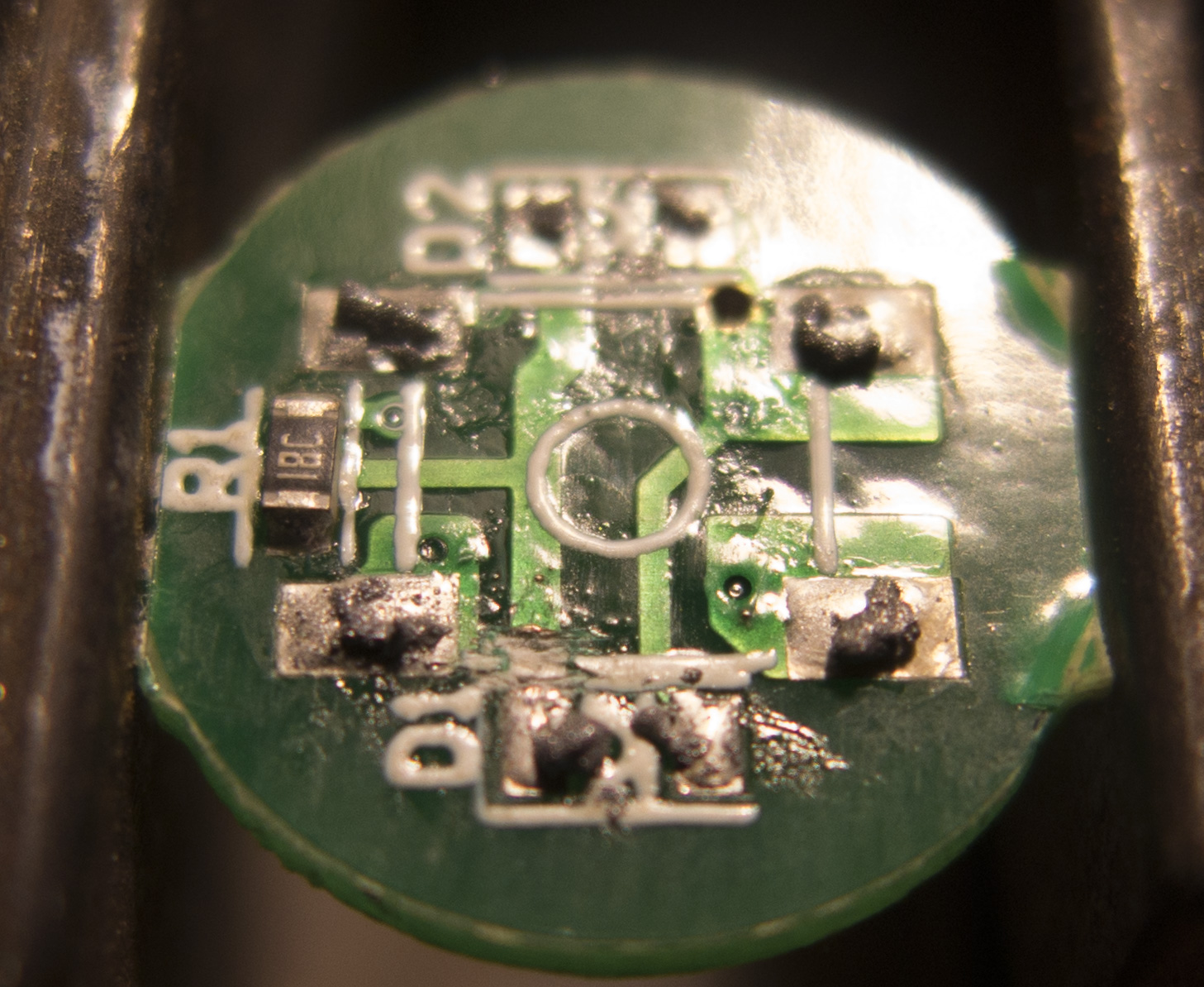
add resistor and wire
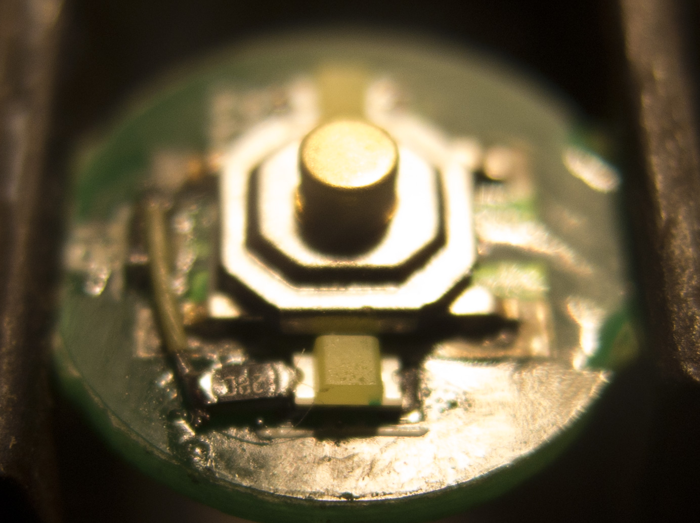
2 white LEDs with 19.1kOhms each
Lots of nice tips here on fixing issues. Thanks for posting up all and keep them coming. ![]()
Got two Q8 today, measured about 5250 lumens with the first one and 4820 with the second one with Samsung 30Q. Did the usual modifications at the tailcap with the first one (some cleaning, thick wires over tail PCB traces, spring bypasses). Gained about 1000 lumens for a total of 6250 lumens. Easiest mod ever, like it.
And also flashed my own firmware without any problems.
What do you mean by “thick wires over tail PCB traces”? Could you post a picture?

Thanks! :+1:
But what is the purpose of this? And the red wire?
He cut the traces, red wire is for a clamp meter
… and I drilled a hole in the center where a thick wire goes to the other side where the spring bypasses meet.
Strange why didnt you simple used the hole on the spring pad to wire the bypasses?
Usually I wire bypasses inside the springs but with double springs it seemed too narrow and fiddly. Maybe next time.
When I do this sort of thing I like to remove all of the original solder, e.g. using solder wick.
After a few scandals about toxic Chinese exports, you can be pretty sure that lead-free solder will have been used, some is excellent when used under tight process control, but most is not.
Thankfully, good old tin-lead solder and paste is still available, I use nothing else, it’s like night and day. when DIYing, but when mixed with the original solder it is never quite as good.
Nice mod, by the way.
Wow! I’m going to have to learn how to solder. :scared: 
Whew.
I wish someone would start selling aftermarket performance modification parts like that.
Make new tail PCBs with those beryllium copper magic springs.
And bus bars instead of wires and traces.
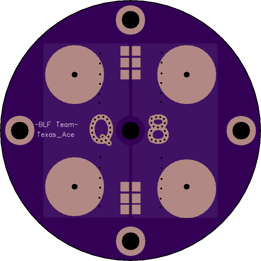
Acrually I designed a Q8 2S/2P tail board, not hard to make one for 1S/4P, but modding the original is easier

Steel springs are fine when a lead bridges them, its easy with boards that have a vias in the center of the spring
I think DB Custom half jokingly suggested replacing the whole thing by a copper plate. You’d loose the loop for the clamp meter but you’d remove PCB resistance and improve contact to the battery tube. And it would be all shiny ![]()