I got around to doing a spring bypass yesterday. I removed the std inner springs and bypassed with 20 ga wire. I had already cleaned the driver board contact rings in the head and reamed the too small board holes out; which got the driver mounted flat with new 3.0M brass screws. The standard spring bypass with 20 ga wires netted an increase of 1322 lumens for 7139.
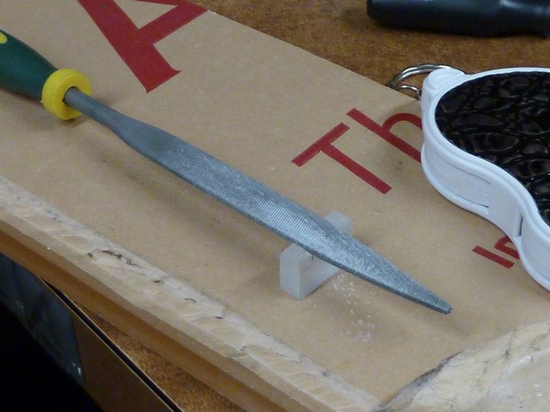
Tonight I finished a 1/16” thick copper plate for the tail, soldered in single springs and bypassed them with 20 ga wire. That netted an increase of 122 lumens for 7259. That was a lot of work for smallish return. A lot of work as I cut the plate by hand then filed it round to the scribed line. That was with steel screws, my brass ones are maybe a week away still.
Next, when I get to it, will be larger wires from driver to MCPCB.
I do have a second Q8 that I’ve put the brass screws in, and a third on the way somewhere.
If you’re changing emitters on the stock copper MCPCB make sure you use enough solder paste on the thermal pad, the pad is low like the SinkPADII’s so you have to fill it with solder or your emitter will bug out. Had that happen with one XP-L2, thought it was dead, dimmed, then quit working…. turned out to work fine on a Noctigon so I put it back in after clearing the board and using masking stencil to repopulate with Kester solder paste. Working now, but somewhere down the line I’ve dropped lumens, no longer doing 10,212… only making 8970 now on the same cells fresh off the charger. The only thing different is I’m back to Narsil from Anduril, can’t see how that would make a difference but perhaps Narsil has a bit lower Turbo cap? Don’t know.
Ok, so I’ll test the XP-L2’s with the stock tube/tail pcb/springs and get back in the morning….
Driver mod done, stock FET swapped out for a 404DP and 18awg Leads soldered to all 4 pads, LED’s swapped out for XP-L W2’s 6000k-6500k, MCPCB shelf tool marks ridges removed and polished, AS5 thermal grease. All contact surfaces copper pcb, driver shelf in head, ano has been removed, and polished, cleaned and then rubbed/buffed with NO-OX-ID “A” Special, then a light coat left, on all contact surfaces.
Measured 27.67 amps at the LED leads, on 4-VTC5A’s with my Fluke 36 my UNI-T is down hard!
Recap with driver pic…
Meh, it’s brighter…… :sunglasses: :+1:
Anybody want 4 slightly used NW Q8 LED’s……too mellow for this fellow
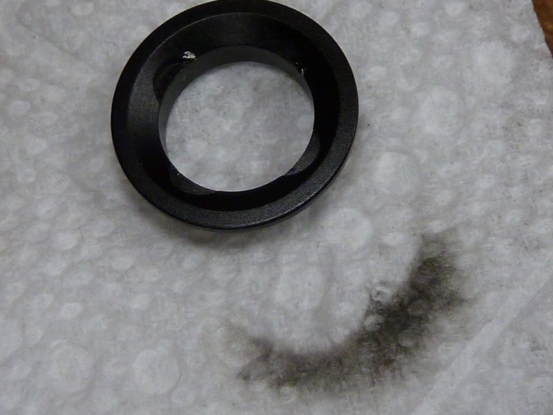
Yep, use medium or fine emery cloth and water, sand paper will tear, wrapped around a piece of square stock, like a 1/4x1/4 or 3/8 x3/8 piece of key stock or something similar, wrap it in the direction that your turning rotating the head,opposite the head threads of course and keep it at a slight angle towards the direction of rotation and square to the surface your removing the ano from, as you rotate it, like dragging it across the surface, keep a steady even medium pressure on it, (you don’t have to HULK out on it) as you rotate. You will see it getting lighter as the ano wears off. It didn’t take very long to do…
Then you can use an abrasive polish, if you wish when the ano looks light enough or you think it’s gone.(I used Comet Cleanser, made a paste out of it, worked really well!) Checked continuity with my meter to the emitter shelf just to make sure, yeah I’m a little anal! :person_facepalming:
Then I used that NO-OX-ID stuff and ran that around with a Q-Tip, heavy pressure as I rotated the head (now you can HULK OUT) Then a very light coat of the stuff and assembled.
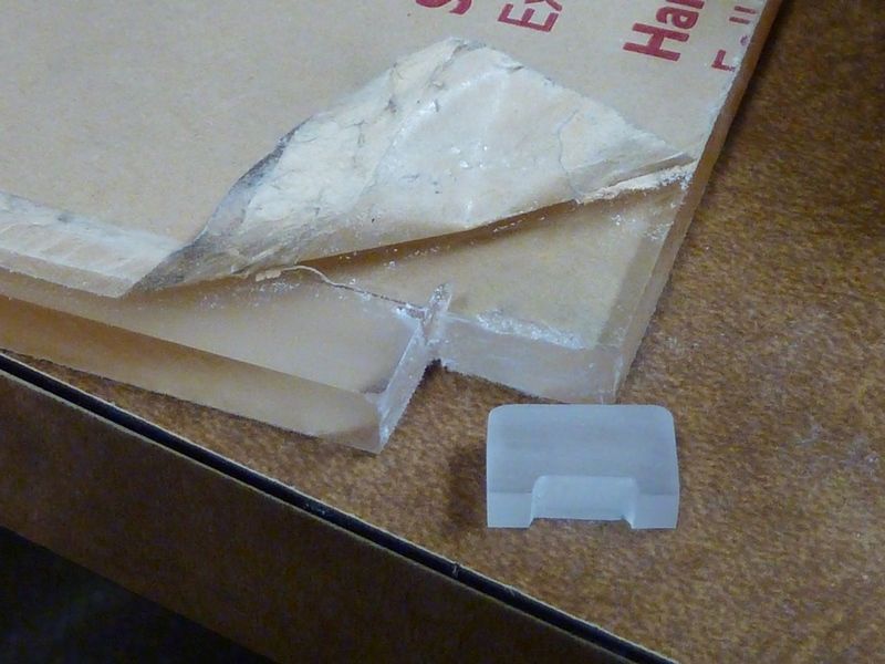
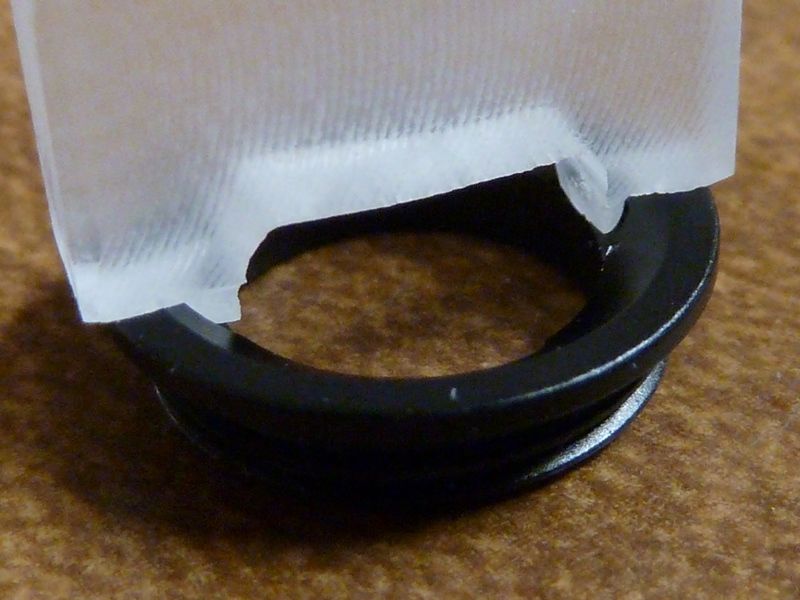
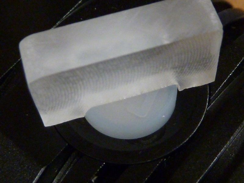
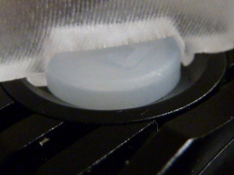
Thanks! It was all done by hand sanding and filing. I like working with that stuff, gets a little messy though. I used smaller files for shaping the 1/2 circles.
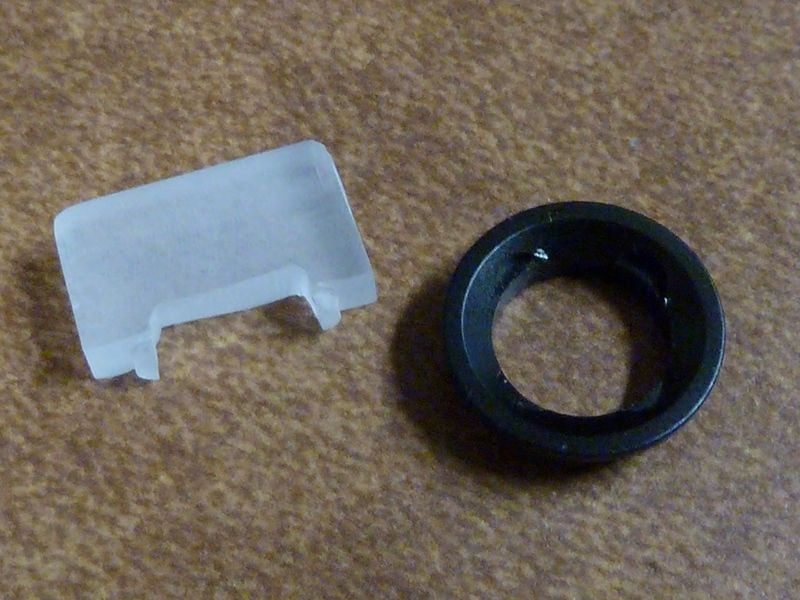
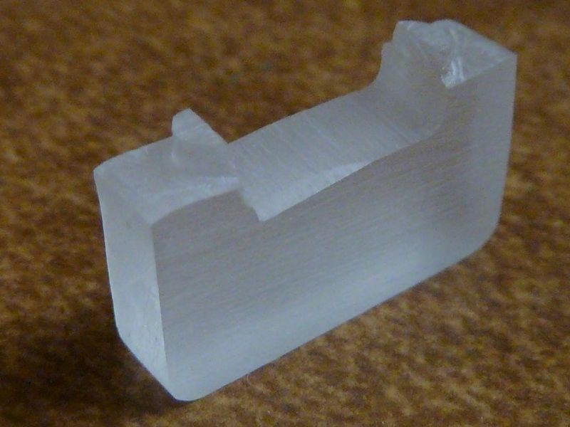
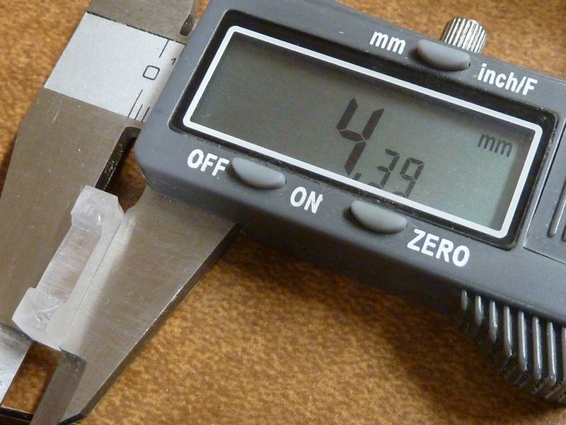
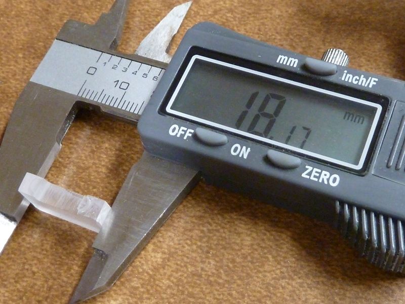
The material started at about 8.25 mm thick from that scrap piece, sanded down to 4.4 mm. A mech designer at work said he'd try 3D printing a jig to fit over the button and fit into all four of the 1/2 circle notches. He thinks the material would hold up, but I'm not sure - it would have advantages to fit in all 4 notches though.
They use SolidWorks here @work, but if it works out, I could maybe make a few available.
You mean the SolidWorks files? Thinks that's no problem - I'm not familiar with the standards, but think there's standard formatted files. I'll have to ask, but again, he'd be doing it in his free time, favor sort of thing. Dunno for sure if he'll have time, etc., and hope it doesn't take much printing time - it would be pretty small though.
I have a printer that I borrow from a robotics team I mentor, and I don’t have it home with me tonight. But I got out my calipers and used TinkerCad.com to make a design. There are two slightly different versions, that take advantage of different properties of how 3D printers work. Give them a try and let me know if anything needs to be changed. Or play around with TinkerCad and make the changes yourself. TinkerCad allows you to download .STL files, which is what most 3D printers use.
The software thinks it should take about 15 minutes to print both of them.
So I got RMM’s nickel plated spring and went to install them today. This was my 2nd time soldering, but I was having a really rough time. Several issues:
1) The solder would form into balls almost immediately when my soldering iron would make contact with the solder. And these small balls would not stick at all. I am using a 2 in 1 wood burner/ solder from harbour freight (I know, cheap). Is that perhaps the problem? Also I am using this solder from MtE (MG 63/37 ).
2) After removing the original springs, there was all this leftover solder and glue type material left over…what is the best way to cleanly get rid of that stuff?
I was reading that the forming of the solder spheres is due to not enough heat from the soldering iron. I tried 3 different tips, 2 of them never used, and same result
I thought I had posted what I measured the output of my Q8 stock when it arrived 5 days ago... I could not find the post but I always write down everything...
Stock when it arrived using 4 well matched 30q's fully charged I got 5805 lumen that dropped quickly to 5375 lumen.
I finally had a night off so I got to do my clean up and do spring bypass.
I took my time and made sure that I did the best that I could do, taking time to build the solder a little around the screw holes on the tail PCB.
I cleaned all the dirty lube and screw holes. Just put fresh lube on all of the threads and O-rings and using the same 30q's freshly charged my Q8 hit 7267 lumen...
For any that do not know my tube is really hard on any light. I keep it calibrated constantly. Every light I can add to the list I add. I have over 50 different lights logged to confirm my current calibration.
It almost always very quickly tells on any light over rated.
The first light to make claimed lumen on first try was the MT07S.
My point is that as greedy as my tube is I just hit over 7k lumen from a light costing less than 40 bucks.
You guys did an amazing job. I honestly did not think the emitter could hit those numbers...
My hat is off to everyone involved in this build. This really puts budget in budget light forum.
I think I will leave it where it is... 7k from a light the size of a soda can lol...
Thanks again..
I really hope that I can get the time to get involved in one of these..