Sort of a combination of those things Ian, the springs are typically gold plated steel for mechanical function, so the bypass is always a gain and in the case of 4 cells and 4 emitters it turns into a large gain. Not that factory lights are bad for having springs made of steel but in this case the ease of modification makes it a big plus. Welcome to the world of improved EDC! ![]()
Hi Dale, the Q8 is a bit big for me to personally class it as an EDC light ![]()
Then again as I am on the list for a GT, then in comparison to that monster, I suppose that you could call the Q8 an EDC light ![]()
In the fall and winter with a jacket or coat, the Q8 is handy enough. When it’s hot out and we’re wearing T-shirt and shorts, well, the Q8 is a bit more difficult to have tagging along. We had a brief taste of cooler fall weather but are back up in the mid 80’s as usual. So it’s T-Shirt and shorts with sandals weather in November. Nothing new there. Need to figure out a good lanyard mount for the tail cap……
Mid 80”s is your usual fall weather ![]()
We don”t normally get mid 80”s in the height of summer here in the UK, maybe 1 or 2 days a year are that temperature & not every year.
It is Autumn here now (fall ?) & the last 6 or 7 nights we have had frosts (temp below 32f) & maybe 50f in the day.
Only good thing is that at the moment it is dark from about 5pm to 7am so 14 hours of dark.
At the height of winter it will be dark from about 3pm to 8am but temps will be down to low 20”s F at night (maybe 10-15F) & daytime will struggle to get above 32F ![]()
![]()
Dark at 3 in the afternoon?
Crimey!
We’re much more likely to be playing with the kids toys outside on Christmas day in shorts and shirt sleeves than to have snow, very seldom does it get snowy here… an ice storm once in a while in late Jan or early Feb, but it can be icy one day and 90 the next, no joke!
The plastic rings for reverse polarity protection are a good idea, something I suggested a long time ago (at least the inner ring), but the brass ring on the driver is too narrow in diameter. Samsung 30Q “button tops” from Bangood for example only overlap this ring at the outermost edge by maybe a mm, or perhaps 1.5. So it might not work for these. The inner piece could work against a reversed cell, but the outer ring might, I think, just prevent the cells from making contact in normal conditions, i.e. a fail.
There does seem to be a disconnect (not a pun) between the actual battery arrangements (radius) in the tube, and the contact surface (brass ring) on the driver. They don’t really match do they ? Actually hardly at all (brass ring too narrow, cell tops (particularly when solder-blobbed) too far apart. Even with BG “wide flat button tops” they only touch the outer periphery of the brass ring by maybe 1.5mm, judged by witness marks. Solder blobbed things only just touch the very outer edge and maybe could be a bit perilously close to the two driver screws, in the limit. And the battery tube only just contacts the driver PCB at the outermost edge,by less than a mm, after a bit of adjustment, at least in mine.
Just saying, it is what it is, it does seem to work well, regardless.
Facts: diameter of brass ring outer edge 31mm. Distance between centre of cell positive contacts in situ in tube, at least 29mm or more, depending on slimness of cells (I measured 32mm with mine, and some older slim cells), so solder blobs will be riding on the edge of the brass ring (they do, it cuts into them) or “button tops” may ride over the brass ring, by a rather small overlap (they do, and the witness marks show how little contact there is)
Awesome! Thanks! 3000 lumens is amazing for 3.3V cells.
I dont understand all this hand measures and etc. Since Miller had shared 3d model files with pdf drawings, you can easily check any dimensions.
Centers of cell holes are laying on 27mm diameter. If hole is 19mm and cell is 18mm, we have 1mm gap to the both inside and outside directions. In my experience cells always go outside, so lets say that centers of non-protected cells are laying on 28mm diameter.
Yes, this is just 1.5mm overlap, but dont forget to add half of button width to this measurement. I.e. with 8mm button top you actualy have 8/2+1.5=5.5mm overlap.
I think head with driver place, and battery tube have ideal central alignment, the only problems may be caused by bad driver ring alignment. Both inner and outer diameters of ring dont match driver pcb mask, that why most driver ring have 1-2mm offset.
I got 30Q buttom tops from an european seller with different button caps. The (not completely) flat top of the caps has a diameter of only 3 mm. This caps seem also weekly bonded, meanwhile one cell lost its cap already.
Not nice if this had happened inside the light.

big question is: which european seller?
Well, I’m sorry, but I can’t find the bill and don’t want to blame the wrong seller. When ordering lithium cells in Europe I only use 2 well known stores, so it must have been one of them.
Another picture: on the left the good old Banggood 30Q with solid button cap, next one of my new cells with cap still in place, and on the right the cell from the same batch with its lost cap.

The Banggood button top cell has an additional clear shrink wrap layer, which should hold the cap in place even when it gets lose (I guess).
I’ve got the same button tops, but on Sony VTC6. I’ve ordered them from batterijservice.nl, but it looks like Nkon sells the exact same button tops.
To prevent damage, I’ve ordered some clear shrink wrap so I can fix this…
I measured my torch, and agree with your figures. The cell holes in the tube go all the way to the edge, 46mm in my case. My un-protected 30Qs are 18.5mm diameter. The contact surface (the flat bit, not the total diameter) of the wide flat buttons on them is 6mm diameter. The brass ring is 31mm dia.
So when the cells are fitted and laying against the outer part of the tube, the centre of the buttons is on a diameter of 27.5mm, overlapping the brass ring by only 1.75mm. The wide buttons increase the overlap by 3mm to 4.75mm which is fine. provided the brass ring is centred. Mine is off by about one mm so worst case, the overlap will be reduced accordingly, for one cell.
However for my solder-blobbed cells, which are 18mm diameter, I have filed the top of the blobs flat to create a contact surface of about 3.5mm diameter. Before I flattened them, the rounded blobs were effectively a point contact. With these measurements I now have 3.25mm overlap, minus the eccentricity of my brass ring. Before I filed them there was just 1.5mm of overlap, assuming the blobs were all perfectly centred (they weren’t) which I considered too little, and the soft solder was showing rapid wear.
The bottom line is that yes there is overlap but it can be rather slim in the worst cases. Wide flat button tops seem fine, but if solder-blobbing you might want to consider filing flats on the blobs to gain a little more contact area and wear surface. I don’t have any narrow button tops to measure.
Tom e if I lived anywhere near you I would show up on your porch with my hat in one hand and my 2nd q8 in my other hand, literally begging for u to work magic on it. I say 2nd q8 because the first one received the ugliest, half assed spring bypass that the world has ever seen. Accomplished, of course, by yours truly. Even though it is so horrible, it still increased my output by nearly 1000 lumens. I have a new solder iron ordered because the crappy 80 watt unadjustable iron I have is way too hot, and I am way to inexperienced to use it correctly. The amazing job you, and many others on this site do modifying their flashlights makes me green with envy, and my skills leave me with blistered hands and melted circuit boards. Oh well I will try again with my new iron as soon as it gets here and my blistered hands and blistered ego both have time to heal.
For Joey and others, some basic soldering tips that work for me:
- you must see clearly what you are doing - use drug store type magnifying glasses if need be, and get plenty of light on your work -- light is very important. I use a headlamp even though the room is brightly lit.
- use plenty of flux. Doesn't matter if the solder has flux in it already, use separate flux.
- clean up your work - use isopropyl alcohol, 90% min, available at most good drug stores, think at 91% or so
- use a flat chisel tip iron, small flat chisel tip - never a pointy iron tip. The flat chisel one gets more heat to where it's needed. With a small flat chisel tip, I can solder any small things without issues - 0603's, 7135's, etc.
- I always put the solder on the iron tip, then apply to the wire, etc., being sure to heat both surfaces - this frees a hand up
- always pre-tin pads and pre-tin wires - things bond much better
Always interesting to see how different people achieve similar results through differing methods.
I NEVER use a magnifying glass, use only ambient light, and use the stock chisel tip or a beveled 1.2mm tip on my iron.
I NEVER use flux, rely only on the flux in the core of the 0.031 Kester solder.
And I seldom have to clean up a board, if I do I use de-natured alcohol for it’s purity and no water content.
Establish a format that works for you, it might help to take tips from others or it might not, but familiarity through experience in the use of your equipment in your settings usually leads to a work-flow that you are comfortable with and that’s the key element, being comfortable with how your equipment works. This is an element that is acquired through lots of practice. Just do it, and as you apply you will learn and your skill set will grow.
I used to be so scared I would mess something up, be unable to replace a part, but I’ve learned most things are replaceable and even repairable, so the sheer confidence level through trial and error is what will get you through most of it. People here are always quick to help should one run into something they haven’t seen before and that goes a long way towards giving a new modder the insights to plow ahead.
One thing that always seems to hold true is that there are multitudes of ways to see something, varying ways to achieve a goal, and of course a lot of opinions. As usual, practice makes perfect. So forge on!
Remember, a professional is a trained amateur. Everyone started somewhere…
And as an addition to Tom and Dale: we love good pictures of screwed up modding attempts!! ![]()
(and we will cheer you up as well ![]() )
)
Dale, this is true the screws are 0.2mm lower than positive contact plate, but the problem occurs if one battery is upside down. The screws are not a big problem the problem is to put the battery upside down. There is a high probability that a short circuit will occur on the last bit of tightening of the tube. If the batteries are inserted correctly then everything is fine.
If you are convinced that no problem with screws OK then. This means there will not be a problem to you put one battery upside down and let us know if anything happened. (I'm kidding)
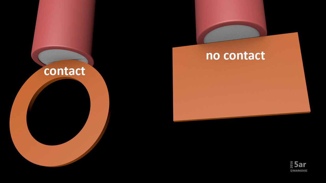
The picture shows why a short circuit occurs when the batteries are inserted upside down. I hope it is clearer now.
Tom E did the test and we know the result. He was lucky that springs collapsed before the batteries became hot enough to burn=explode. Bypass wire can slow down the springs collapse and the question is what would happen then???
Be careful, maybe it's best to avoid this weakly bonded cap battery.
We should organize a competition in upside down inserting the batteries in Q8. ![]()
![]()
The upside down battery problem is I think a genuine concern, particularly given the way the brass ring only just contacts the centre of the cell.
As long as the wrapper is intact and the cell doesn’t tilt over too much you might get away with it, but obviously Tom E did not, though his un-bypassed springs saved the day.
The suggested plastic piece in the centre of the brass ring is a good safety measure I think against cell reversal. I suggested it way back but it didn’t receive much enthusiasm then.
The outer plastic ring I don’t think would work reliably given the way the cell positives overlap the outer edge of the brass ring by quite a long way, unless precisely dimensioned knowing all about cells in the marketplace, I think it is more likely to just prevent correctly fitted cells from contacting the brass ring.
The issue of the the driver screws being so close to touching the cell positives, when cells correctly fitted, is another matter that I have worried about, but hopefully won’t happen in reality, several things would have to go wrong simultaneously.
Poor badly welded button tops coming loose as shown, or lumpy solder blobs, would be my main concern. Wafer head screws with maybe a few coats of nail varnish or epoxy to insulate would make me happier. Better still, no driver screws at all, just a couple of dollops of e.g. hot melt glue to secure, perhaps with a couple of studs or grubscrews in the screwholes for location.