I think it has been said before that 350mAh 7135 regulation chips will many times come in around 360 or 365, it’s the higher than that select ones that they call 380mAh. So you are more likely to get more from the 350mAh labeled chips than the average 380, if that makes any sense. That would explain why you’re seeing 3.65A instead of 3.56A. Dunno…
Thanks DB on the 7135 info. For wires I went 22 on the driver spring and 20 AWG on all the others. Plenty of room in there.
There was a deal on the BD06 last week for $19. Worth every penny. I like the build of it for the most part. Plastic spacer under the driver retaining ring could use some redesign to omit. But the 105 minimalist driver that still charges is nice and still using the 1288 as a side SW was a surprise. Side SW push is stout with the little extra spring under the button. Don’t see it getting turned on by accident even if in a tool bag. There are some rings in the spill but a pretty nice spot from the XM. This thing could certainly take a beating for years. With the extra 7135’s it gets warm in hand, I don’t think thermals (timer or sensor) are needed. . I have grown fond of the 26650 and tube size in hand.
Do you mind telling us how do you disassemble the board?
I also have this torch and would like to do some mods but the board seems to be glued.
wondering if anyone can help, I’ve just done a spring bypass on the driver and tail switch springs on my BLF A6. I now only have high mode, it wont switch to any other modes. Does anyone have any insight as to why this might be??
Thanks
DoNkEyConN
That usually happens when the led-minus connection touches the body somewhere, thus bypassing the driver entirely and the led is directly connected to the battery. It can happen somewhere on the driver board or in the wire (insulation damaged and exposed wires touching the body), or even on the ledboard.
thanks for the info Djozz
I’ve checked all over, resoldered + and - to the led star, checked the wires and nothing sticks out as abnormal. mkght have to try a diffent driver see if i damged the last one somehow.
Test parts out of light. Just dont let the LED lit for more than a second if it is really gone DD.
My guess is the LED MCPCB is twisting as you tighten the head. With the MCPCB twisting it is pinching a wire in the through hole. Sometimes silicone heals the cuts so it is hard to find without bending the wire to open the cut. BLF, Noctigon and similar boards are nice but the edges are sharp.
To help stop the twisting I lube the Oring on the lens and push on the lens and reflector with a thumb as I tighten the bezel.
Also make sure the wire insulation wraps up and over the MCPCB to the solder pad. As I solder the wire I push the Iron on the wire to flatten the connection where the space is limited. Solder blob on the pads may be touching reflector as you tighten it.
And not to be insulting but you do have the plastic spacer around the LED to reflector? I have lost them during assembly or put a light together and then saw the spacer sitting on the bench.
Thanks, VWpieces,
all good ideas, have checked everything you mentioned. I did find the MCPCB was twisting as I tightened but couldn’t find any cuts in the silicon wire. when I had the bezel off I placed the reflector on with the spacer and the solder wasn’t touching but resoldered and flattened out as you mentioned. Put it back together but still, high mode only :cry:
No offence taken at all mate, im fairly new to this so any suggestions are appreciated.
ive got some drivers on the way so will replace and test when they arrive.
My first guess is that you fried the FET with heat from the solder while doing the spring mod. Whenever working on any of these drivers try not to let the driver get too hot for too long. If your solder doesn’t stick the first time let it cool down for a bit before trying again.
Thanks vw ![]()
The original mod was done a while ago so I can’t remember for sure but the LED MCPCB is probably glued with some cheap compound that should come off fairly easily by twisting slightly with long nose pliars in the wire holes.
There might be a plastic retainer ring in there too.
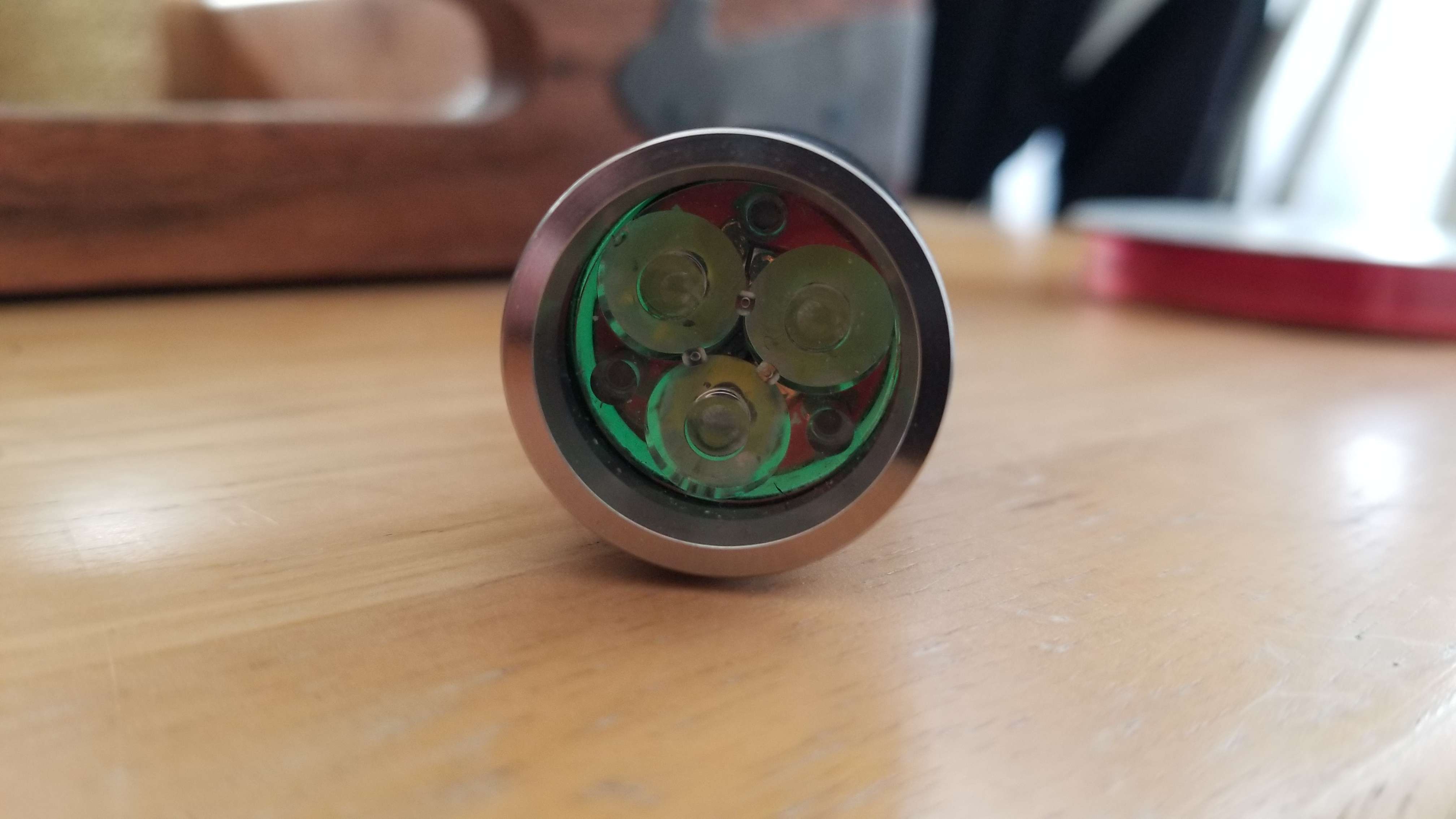
Sunwayman P25C converted to triple xp-g2 s4 2b on a noctigon. Carclo 10507 and stock driver.
thanks for the suggestion, ill keep that in mind next time.
Direct drive only is usually a short to the negative lead, bypassing the driver and going direct drive. This is typically because the reflector is touching the negative lead or the negative lead is shorting on the MCPCB. I like to use Arctic Alumina Thermal Adhesive to glue the MCPCB in place so it can’t twist. If you’ll check the negative lead path, it could be shorting on the side of the pill at the driver, or pinched/cut at the emitter shelf or the edge of the MCPCB. Given your lights symptoms I’d be tracing the negative lead. Fix that and if it still acts up, well then it’s time to dig deeper. ![]()
Thanks DB Custom,
I have tested the light with the reflector and bezel off, the still high mode only, so don’t think its shorting on the reflector/bezel
maybe I should try with a new Negative wire, don’t think I have any spare right now though.
Thanks CRX, will try! ![]()
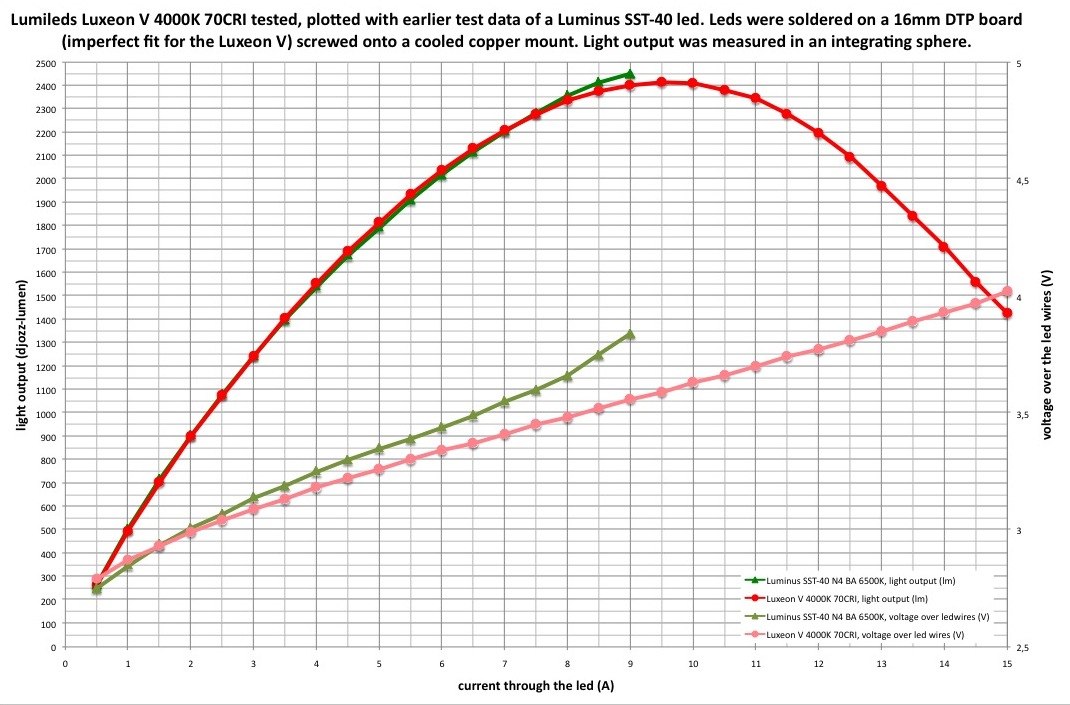
I have built Jaxman E2L with Nichia 219C sm503-D240-L1-R9050 and LD-B4 9Amp 17mm constant current LED flashlight driver. The biggest challenge was to solder everything on MCPCB, especially a small transistor. Also I had to sand the MCPCB to get it to fit in the light. After first try I checked MCPCB with multimeter and there was a short, so I sanded it “upwards” (so top black layer is folded towards leds) and it helped. The hole in the shelf was also drilled to fit more wires. Everything togheter produces a beautiful tint. According to this review it should make around 2400 lumens at 9 amps and 2000 lumens at 7 amps. At 7A (2000 lumens) stepdown occurs after 70 seconds in room temperature. It’s a bit dimmer than D4, but at least output can be sustained for over a minute and even longer outside in lower ambient temperature. There are beam shots and skin (?) shots in the album.

Very cool build g_damian,
did you do any thermal sinking to driver?
and good find on the MCPCB conductive layer and sanding it back.
I got some LED4P stuff for the single Luxeon V on 9A in S2+ build
Thank you ![]()
I’ve used “B” version of the driver, so the mosfet is on MCPCB, not on the driver board. According to the data sheet, additional thermal sinking in that case is not necessary.
I’m also going to build Luxeon in S2+, also with thermal enhancement kit.
OK, I did get the “A” and thermal kit too. Selected the NTC for the driver, luckily that tiny thing is already on the Luxeon V MCPCB. 3 colors of tails too. Need to check the brightmess, had no idea what to select when ordering.
I ordered 9 amps version, too. Check in this review, 9 amps is max and makes 2400 lm:
EDIT: if you meant tailcap current, here they are: