Convoy S2+ Mod With A Lighted Switch
Another Convoy S2+ mod? Really, what’s the point? This is probably the most modded flashlight form out there, so why another? Two reasons:
1. To show how easy it can be
2. To show how challenging it can also be
All in all, I had a great time working on this. If someone would’ve said modding flashlights is “fun” a year ago, I would’ve said you’re crazy. Why modify when there are great flashlights you can buy? Take for example the Emisar D4, which is an awesome flashlight for $40. For that price, it would probably cost more to make one. But, what if you want something slightly different? What if you want to try to build something you haven’t done before? For me, and I’m sure for a lot of flashlight modders out there, it is extremely satisfying to create a flashlight that meets all your specifications.
Here’s what I built:


It has 90+ CRI, forward and reverse mode, memory or no memory, moonlight, low voltage shut-off, pocket clip, lanyard, and a lighted switch. The most important design aspect was tint quality.
Here’s the parts list (knowing that the links will be broken at some point in the future, but the descriptions should still be useful):
- Flashlight host ($10.83): Convoy S2+ black flashlight host
- Driver ($9.99): Moonlight Special 17mm Driver
- LED ($4.79): Nichia 219C D240 on 16mm Noctigon - 90+ CRI 4000K
- Pocket clip ($1.10): Deep Carry Flashlight Pocket Clip
Subtotal: $26.71
Parts used for lighted switch:
- Lighted switch ($2.99): Astrolux SC/SS/S2/S3 BLF X5/X6 Flashlight 2LED Lighting Switch For DIY
- White tailcap cover ($0.71): 16mm x 8mm Tailcap Switch Cover
- Omten 1288 switch ($0.36): DIY LED Flashlight Reverse Clicky Switch 12mm x 8mm for LED Flashlight - White (5 pcs)
- Plastic washer ($0.21): 5/16 in. Nylon Washer (3-Piece per Pack)
- 2 Switch LEDs ($0.02): 100 Pcs 5 Colors SMD 0805 LED Light Red Green Blue Yellow White Assotment Kit
- 3 Resistors ($0.01): 400pcs 0805 20 Values 10Ω-1MΩ Assorted SMD Resistors Assortment Kits Set
Subtotal = $4.30
Total costs = $31.01
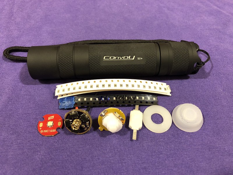
Here are all the parts (minus the pocket clip):


Here’s the simple part of the mod.
This requires minimum soldering skills and can be completed within an hour.
The S2+ comes with a threaded pill that is very easy to work with. Unscrew the pill counter-clockwise all the way out of the flashlight head. Then unscrew counter-clockwise the driver retaining ring.


Place the driver into the pill and put the wires through the 2 holes on the shelf end of the pill. Then solder the wires to the contact pads on the LED board.


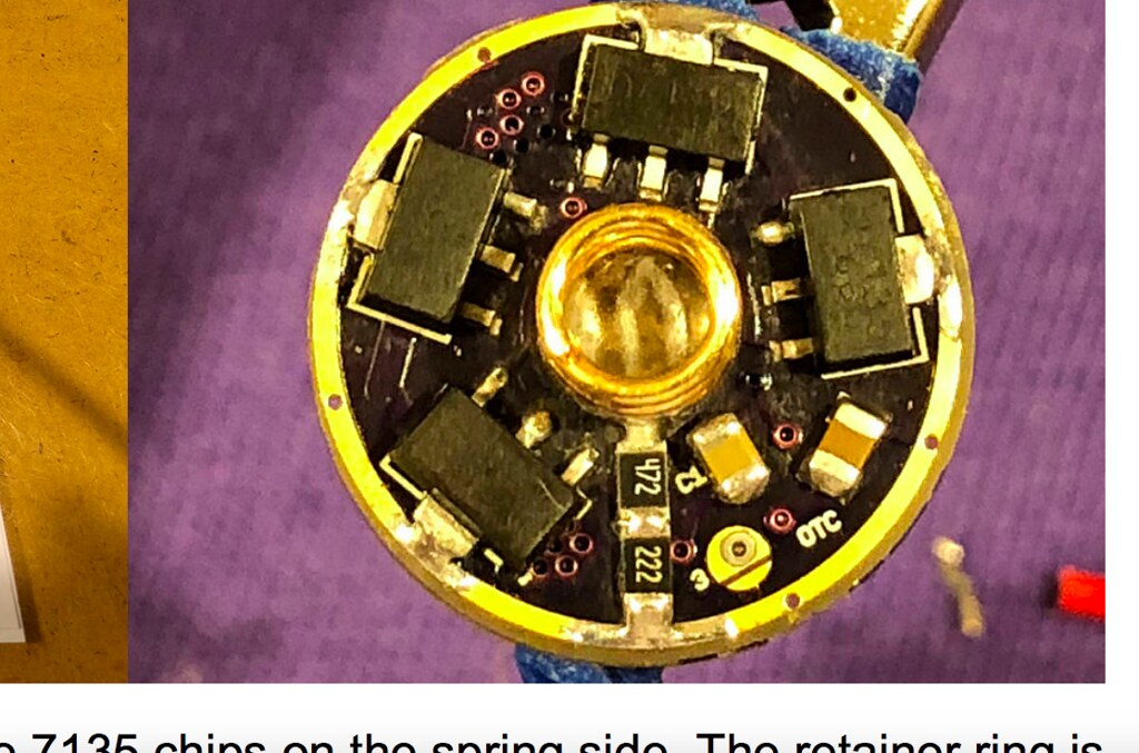
Put some thermal compound on the pill shelf and press the LED board onto it. No need to push hard since it will be pressed in once the head is assembled. Next take the retainer ring and screw it clockwise to secure the driver. Please see below for how I modified the retainer ring. This is not necessary for drivers that don’t have 7135 chips on the spring side, or you could just solder the driver to the pill.


Put the green o-ring all the way into the head, and then stack the reflector spacer, reflector, and glass lens on top of the LED.


And finally, screw the pill clockwise into the head. Then put the flashlight back together and attach the pocket clip. The tail came complete with the switch already assembled. I added some shrink tubing to the clip to prevent scratching the flashlight.


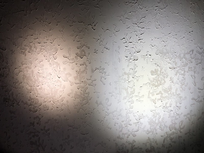
Here’s how the beamshot compares to my JAXMAN E2L. The E2L has triple Nichia 5000K 80+ CRI LEDs. I really like the warmness of the tint in the S2+ and it has a slight rose hue to it. Driven at the max 3 amps, it puts out quite a bit of light and remains comfortable to hold heat-wise after several minutes. And given that it has a CRI R9050 (Ra=90, R9=50), it is very good at rendering red objects.


That’s it! Very easy to have a customized flashlight built by you.
Now for the harder part of the mod, the lighted switch.
I lost track of the number of hours I spent with this. You will need some better soldering skills since the parts are very small, and lots of patience.
For whatever reason, I’m really into lighted switches. I think they look pretty cool glowing in the dark and are useful for finding the flashlight in the middle of the night. There are many ways you can add a lighted switch to a flashlight and this is a must read BLF post if you are interested: D.I.Y. Illuminated tailcap. Some flashlights (i.e. driver and firmware combinations) work just fine with lighted switches. But it seems most of the time adding one will screw up the functionality. It can cause the flashlight to go into the dreaded next mode function, or some other abnormality.
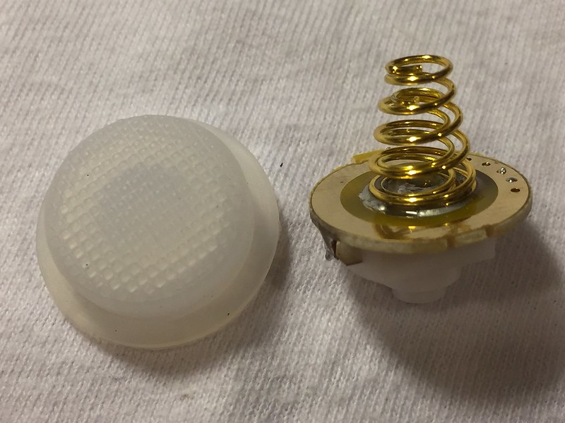
The lighted switch I chose comes with blue LEDs and the part that I really like is that it has dual springs.
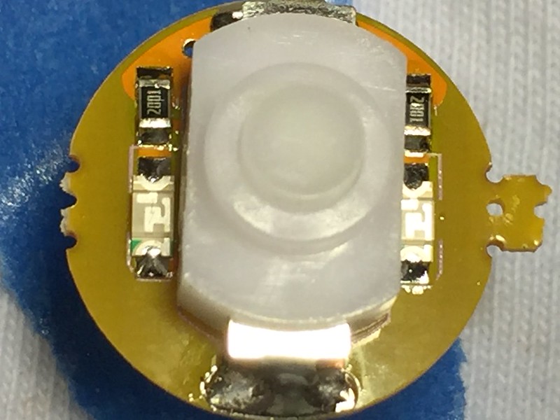
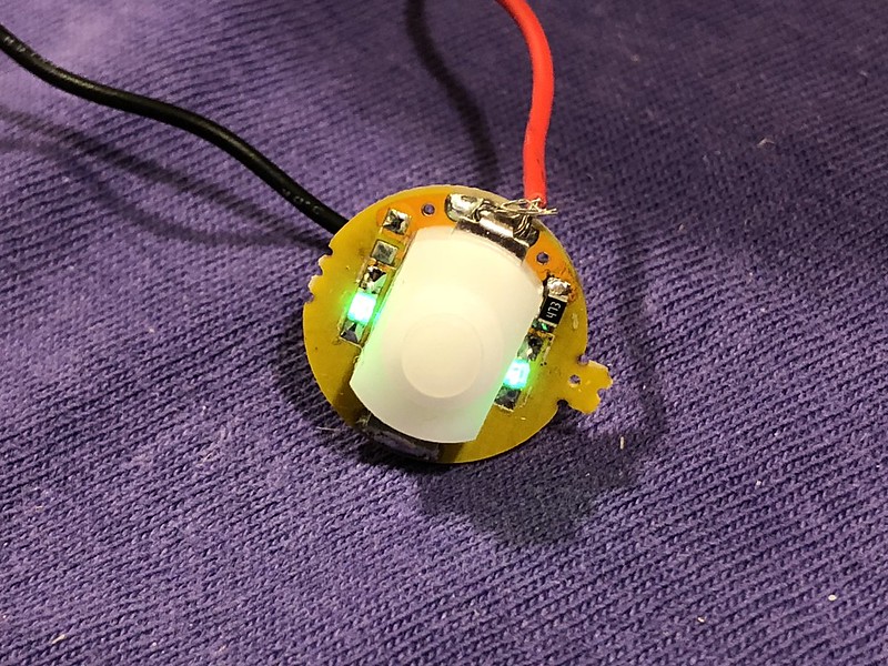
You should first determined the brightness of the lighted switch, which is dependent on the color of the LEDs and the resistor value (ohms). Some colors are brighter than others. I learned that my yellow ones were a lot dimmer/inefficient than the green ones. Initially I was planning on using yellow, but my wife liked green better and I agreed. The higher the resistance (more ohms), the dimmer it becomes. You can choose to have it very bright in order to see it during the day, or just bright enough to barely see at night. I like mine in between and chose a 47K ohm resistor. It can easily be changed later if you think it’s too bright or dim.
I also replaced the switch since this lighted switch comes with a generic switch that has caused me issues (flickering) in the past. The Omten switches that come with Convoys are very reliable.


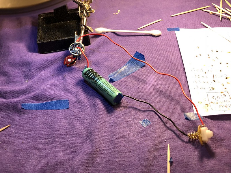
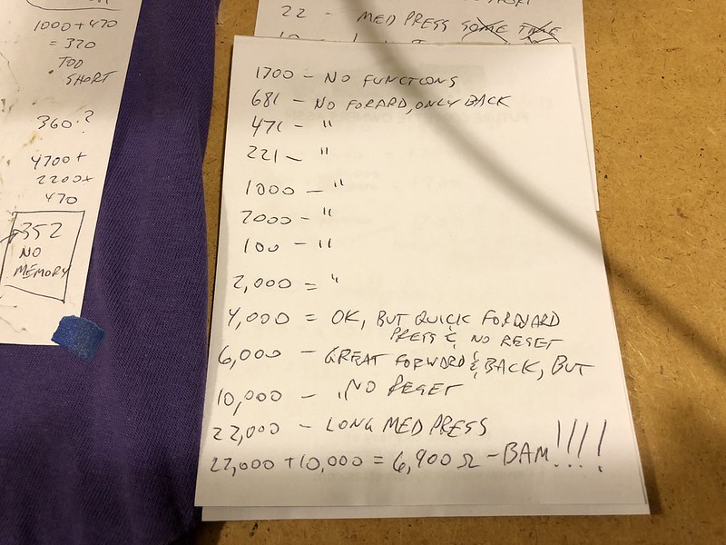
Next is where you need to experiment with different “bleeder” resistors on the driver. The bleeder resistor allows the driver to function normally and is soldered between the positive spring and the negative ground of the driver (i.e. the flashlight body). Normally a 500-800 ohm resistor is needed, but my driver required a 6.9K ohms (4.7K and 2.2K resistors in series). Lower resistance would make the forward press too quick. Higher resistance would make the reverse press too long. And if the reverse press was too long, the mode memory would also be too long or nonexistence.

I also didn’t want to solder the driver to the pill which is normally done when there are 7135 chips on the spring side. The retainer ring is too thick to screw down the driver so I made it thinner by using a Dremel tool. I also moved one of the 7135 chips closer to the spring (circled in red) since it was sticking out farther than the rest. This allowed me to use the retainer ring to secure the driver and in my opinion, a much cleaner look.


Now to install the lighted switch into the flashlight tail. Unscrew the retainer ring clockwise (yes, clockwise) and remove the switch, metal washer, and black tailcap cover.


The plastic washer was a little too big so I sanded down the perimeter. The inside was also too wide over the switch and caused a gap. This made the switch much brighter on one side than the other. So I took another smaller plastic washer, sanded it to the appropriate size, and pressed it into the washer.


The new switch was too wide to fit into the groove of the retainer ring so I sanded down the perimeter to make it fit. Then put in the white tailcap cover, the plastic washer and lighted switch, and screw the retaining ring counter-clockwise to secure the switch.


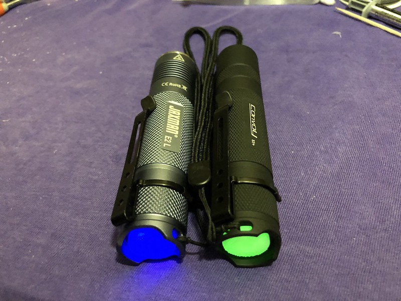
Here’s how the tailcap looks next to my JAXMAN E2L with a blue lighted tailcap.


Some side notes:
- I know there are fans of the “Generation 2” lighted switch design, but I really like the look of the mono-tone diffused illumination of the “Generation 1” design. I measured 0.03 milliamps with the lighted switch so efficiency is not a concern here.
- I know there are drivers/firmware that work just fine with lighted switches, but part of the “fun” was to make this combination work. In hindsight, if I had known how challenging it was going to be, I still would have done the same since I liked the Moonlight Special constant current 7135 driver.
- I could’ve used the switch that came with the S2+, but since I bought some for a previous mod, it was easier to install a new one
- I kept the original lens. I thought about getting an anti-reflecive lens, but didn’t want to risk impacting the quality of the tint.
- I really tried to balance between too much info/pictures and not enough. Trust me, I have lots more pictures that I didn’t post.
I hope this encourages others to modify flashlights. There are no right or wrong ways to mod (well I guess there are some wrong ways and those would be considered lessons learned), it’s just up to your imagination as to how you think your flashlight should be created. And if you run into trouble, there’s always helpful experts here at BLF.
Thanks for reading and please let me know if you have any questions or comments.