Just in case and to cross-check for any errors creeping in?
basically why I was not happy with poor cooling of the boost chip with no viases to the other layers and the option to put more boards on a Seeed 10x10 board in production
and I got no Eagle, no advanced license for it and I think getting used to a 2. program is too much
did a 24-30mm variant
OPA parts got closer together
12mm inductor to save money with better performance

Patiently waiting for the single cell XHP50.2 goodness. Any tests!? ![]()
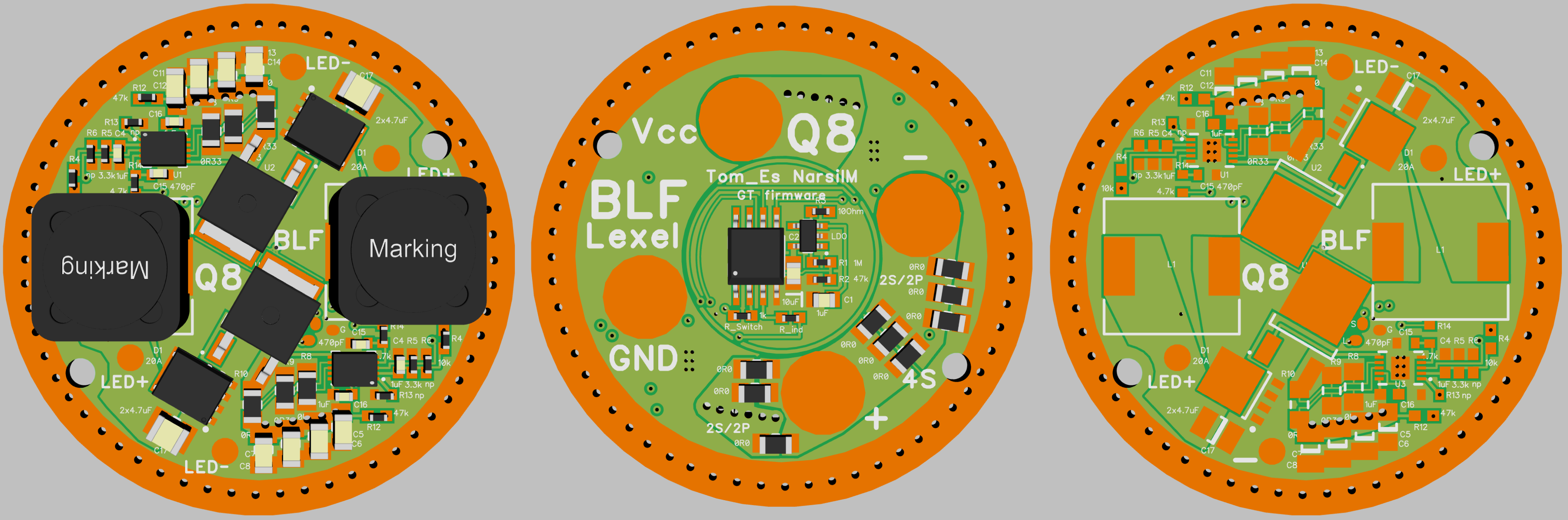
Still waiting for parts and PCB’s to arrive.
I did some light load bench tests, before I fried my driver. The most I did was 8W for 15min in free air, with an XHP35.
No problem for the driver at all. The XHP35 was a few centimeters next to the driver, and was shining on it a bit (when I blocked the light shining on the driver with my hand, it got pretty warm). Even with that, the driver got just a bit warm. If I had to guess, it was around 40°C (with 24°C ambient).
The board that I used was the first revision and had bad thermal properties. The newer boards should do better.
I hadn’t seen it mentioned but would it be possible to use 1 or 2S input to output 12v in lights with extension tubes?
Yes it will be possible
Will this driver be able to be programmed to supply 12v 700ma and lower currents?
There are multiple ways of doing this (3 I can think of right now), so yes.
When the 17mm boost driver is ready, where can it be purchased with firmware already installed? (ready to use)
Noob type question I’m sure… I’ve not previously dealt with newly released BLF designed drivers.
OK thanks didn’t know he sells them directly.
Done:

Awesome, so this allows you to change firmware without removing or soldering anything right?
Yes, very easy to operate and reliable. Using this for a couple of weeks, no failure up to now. Soldering the pogo pins was a challenge though.
BLF Q8 2S/2P and 4S combinated driver 10 or 20A regulated output
XPL, XHP35, XHP50
MF01/MT03 20A regulated 4S Input 2S Output 10 or 20A

Is there a blf style buck driver (good, customizable UI ), that can do 2s input and have 8-11A output for 3v led?
The MTNmax buck stops at 5.5-6A.
With some of the newer leds they dont really stand out from the crowd till they hit 7+A.
I have such a driver in 30mm based on BLF GT design, the boards arrived yesterday
shrinking it to 22mm wont be possible with the limited choice of the MOSFET
I have a small problem reading this OpAmp datasheet here: https://datasheets.maximintegrated.com/en/ds/MAX9617-MAX9620.pdf
To be precise it’s the “Output Voltage-Swing”.
There are multiple values given in the table with various resistor values, but when you scroll down to the graphs, there are two called:
- OUTPUT-VOLTAGE SWING HIGH vs. TEMPERATURE
- OUTPUT-VOLTAGE SWING LOW vs. TEMPERATURE
Now these values from the graphs are much lower than those from the table. For the “table values”, there is a resistor RL connected to the OpAmp, but I don’t know how it is connected.
Is RL connected between the output and VDD/2, to show how near the OpAmp can get to the rail with a load on it, and the graphs, when there’s no load?