The same thing goes for closely packed 144A dies. With single uniform phosphors and silicone layer on top the dies, the photons cross talks is not there. Each time the photon crossing the silicone/air boundary some of it will be reflected back inside, adding more heat. In separated dies like the this quadtrix, adjacent exited photons get absorbed by the nearest walls, adding even more heat.
This is why Nichia uses some kind of reflective wall (soft white silicone) surrounding the E17A/E21A dies - to minimize photon cross talks (so they can cram more E17A/E21A in smaller LES). Without this barrier, we’ll need much larger space.
The barrier also what makes tint shift (from high angle emission, like those found in 144A and XPG3) is minimal with E series
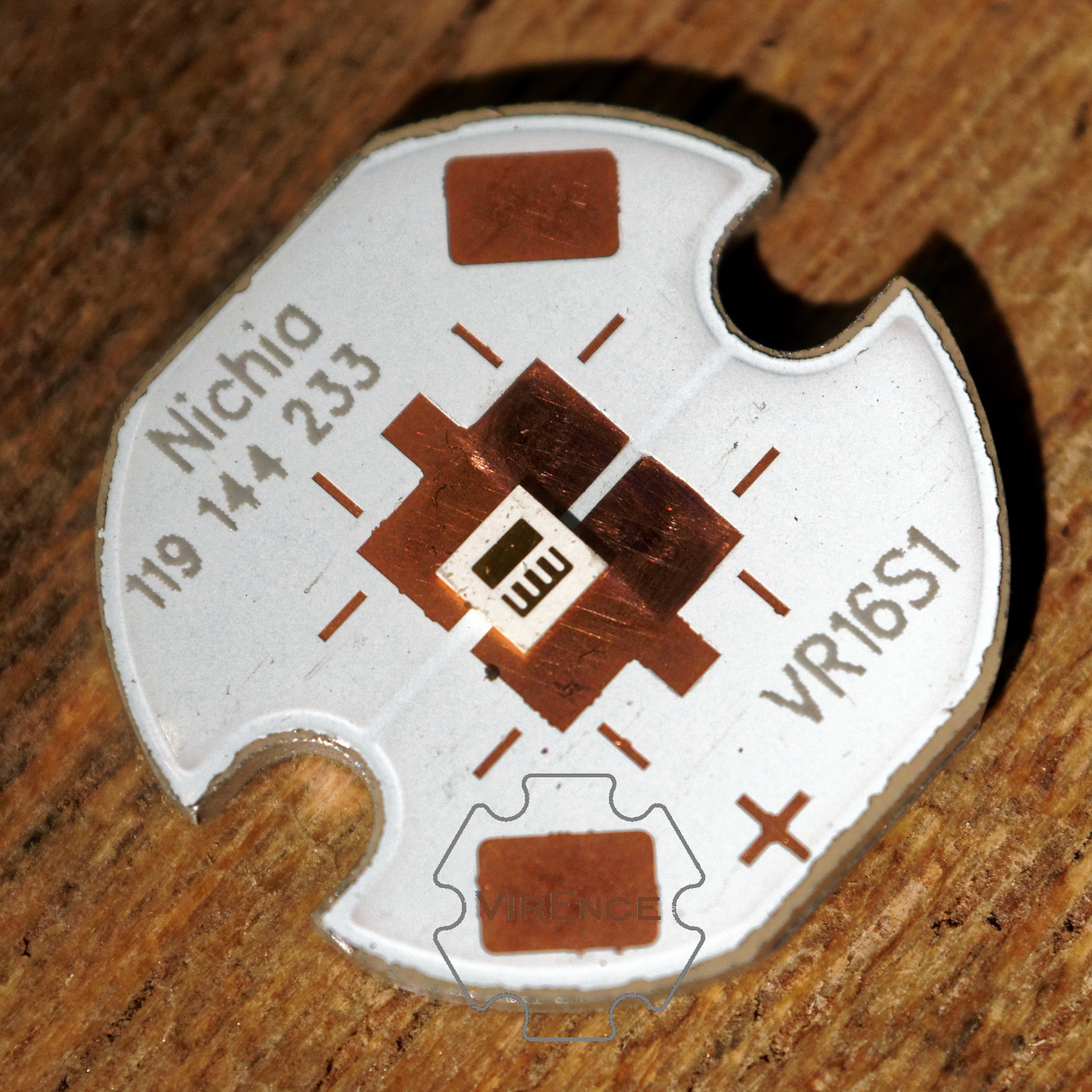
Quick sanding using #1000,#1500, and #2000 sand paper revealed the narrower gap. But the copper trace’s edge is rounded, I have to dig deeper into the crevice to remove the solder masking which I didn’t do. From many previous tests we knew for this particular LED, the junction temperature is far lower than that in the phosphors layer. The top layer will be well done long before the die overheats. Djozz also did his test (E17A & E21A 5000K R8000) with only 1/3 of each pad sitting on the copper trace resulted in approximately same max output limit.
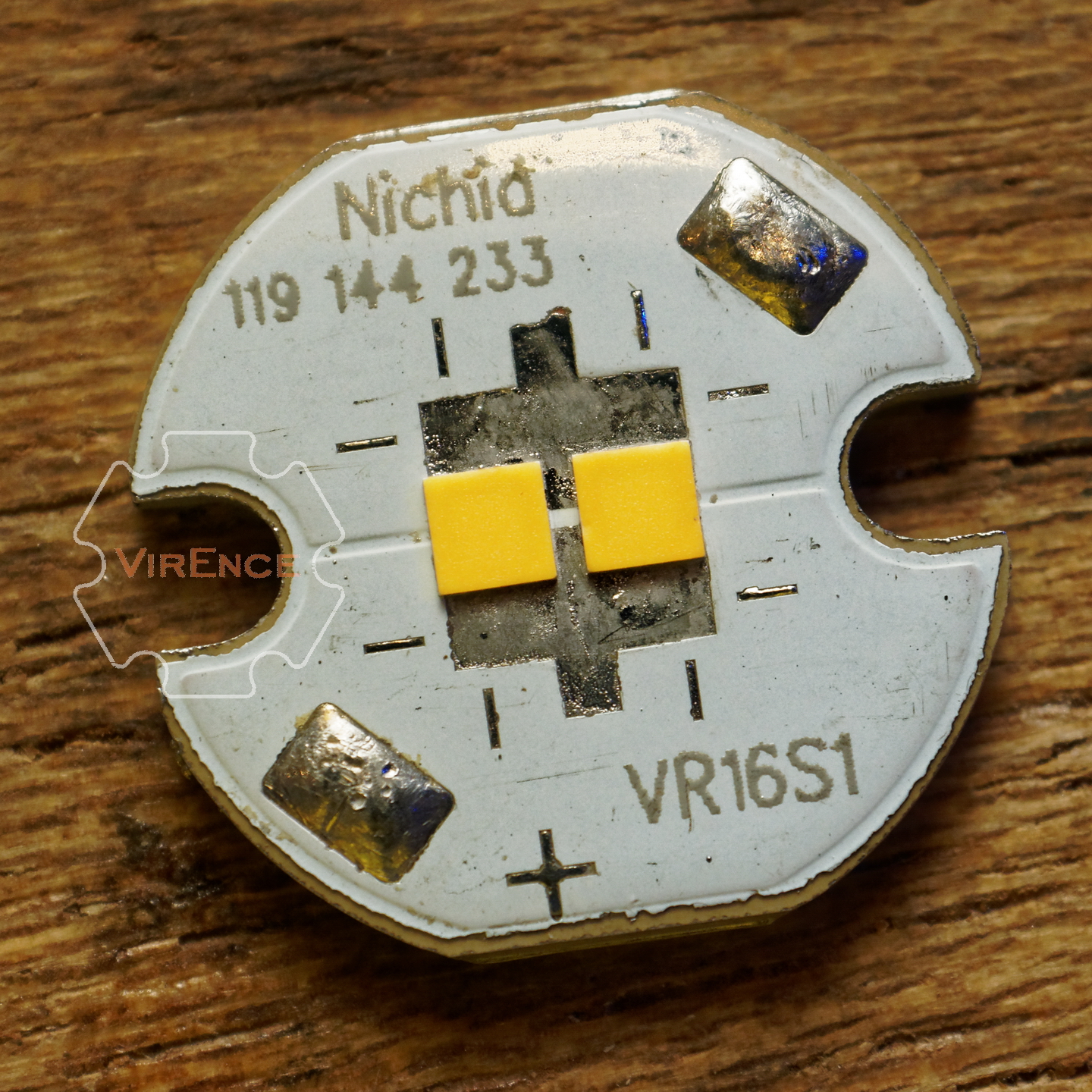
If I didn’t know about photon cross-talks, I would reflow them with no gap. These LEDs will replace those in my scooter (plus more powerful driver). They’re the same sm503 D220 R9080
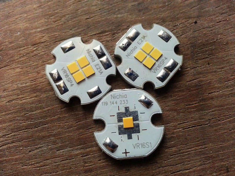
Beauty!
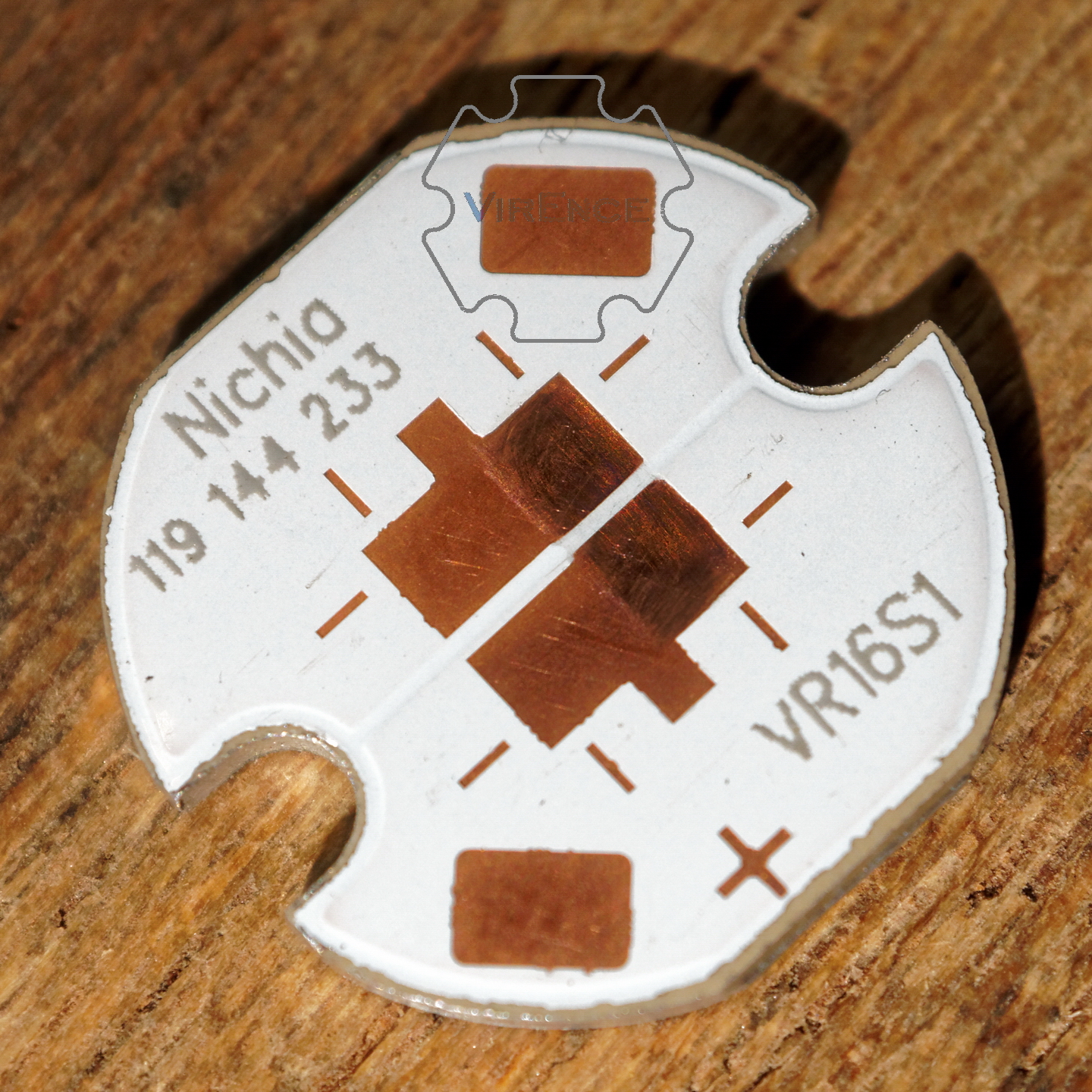
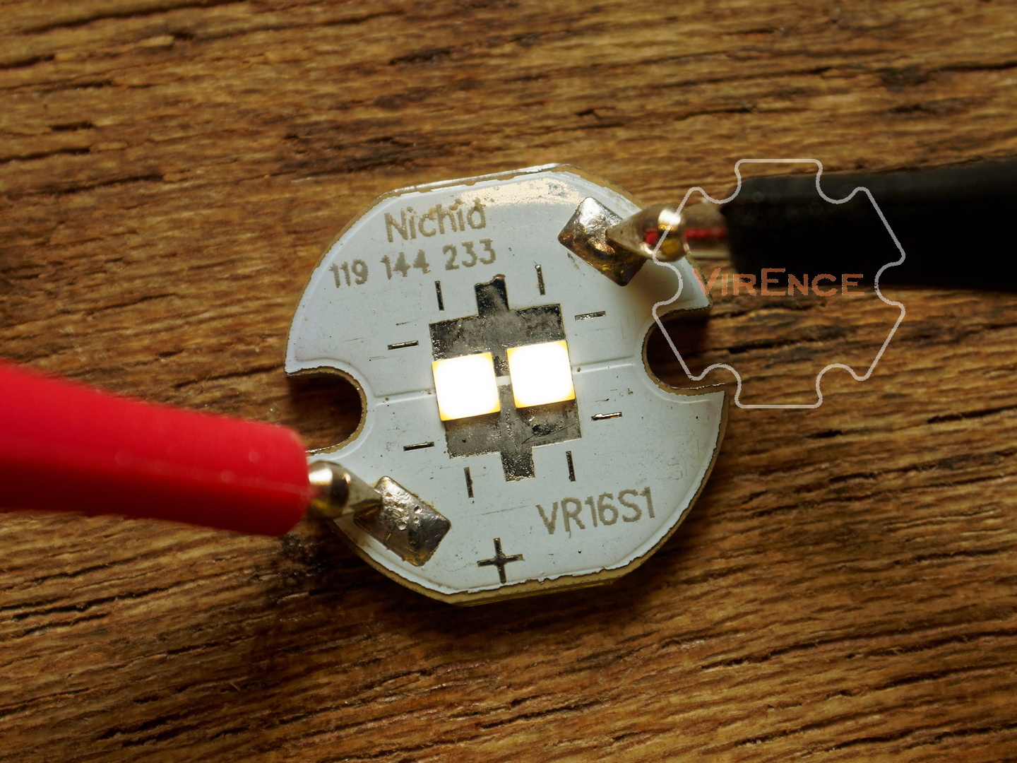
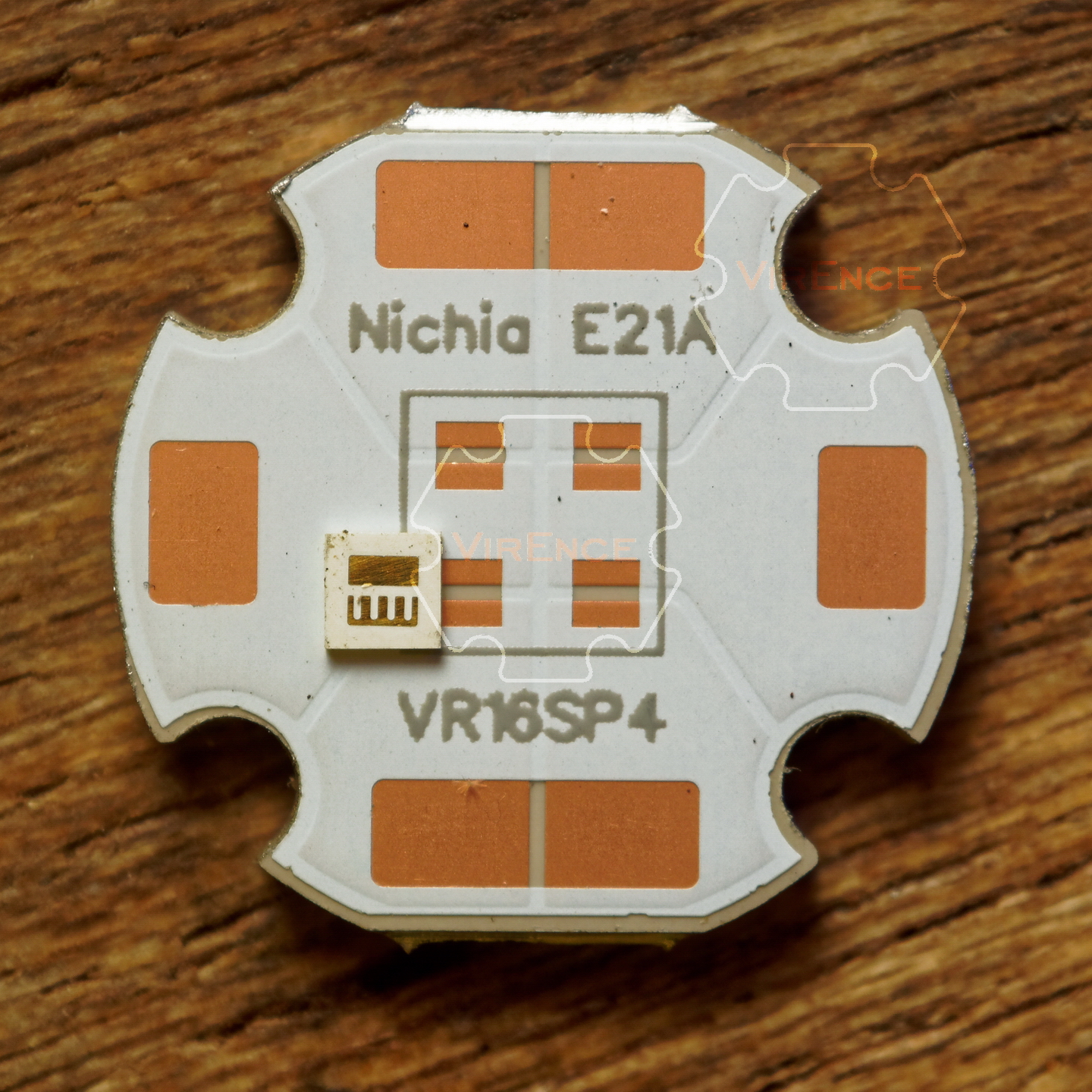
Unlike 2 Oz copper trace in VR16S1, the thinner trace in VR16SP4 is more accurate with well defined sharper edges. This is why I decided to use only 1Oz. copper on it. I’m amazed at how accurate the pads aperture made for it’s tiny size (1,26mm x 0,86mm)
With these quad boards and each of the color temps of the E21 being equally useful in different circumstances I think it is time to revisit RGBW-type drivers. In terms of UI, the closest thing I’ve been able to find is this simple djozz’s hack. In case of quad boards each channel would go to individual E21. This is something I will certainly attempt to do when I have tested these boards with these LEDs.
What would be ideal to have though is a full featured programmable driver which would at least allow one to program current setting for each individual channel (the UI being the same, ie progressive switching to the next LED) but preferably the ability to also set specific switching for an arbitrary amount of modes. For example mode1 = LED1@10mamp, mode2=(LED1+LED2)@1amp.
So far I’ve been able to identify here only one RGBW driver more advanced that the djozz’s hack, which is this one, but the firmware went in a very different direction than what I am discussing here.
While I was considering various options I came across the dr Jones rgbw driver which seems to be nearly perfect fit. I wonder if they are still available? Dr Jones has not been active here for quite a while.
I just received package with mcpsb. Actually the test samples I like more . Edge have ledge (saunds weird, don’t know how to say it in english:))so it should be polished before use.
Sorry about that AEDe, can’t do nothing about it.
I described it earlier when the final product arrived (with pictures too). Of course the prototype finishes were much better since those were made using CNC router ONE by ONE. To cut down cost the final product incorporate V-score for easier/cheaper machining and faster cutting rate (hence the flared outer edges). And FYI, those prototypes actual cost was USD 38,5/pc, and I ordered 60pcs.
I guess for flashlight modding hobby, deburring and lapping the MCPCB can be considered as a routine. I do small batches of streetlights using those boards and still do the lapping too (for the MCPCBs, not me). Those flares can be fix fairly easily using #1000 sandpaper on flat surface.
Clemence, have you ever considered making an adapter for mounting e21s on standard 3535 boards? I mean a 3535 sized very thin two sided board with 2 contact plates on one side (just like one on your quad boards) and 3 standard contacts on the other side?
These would be useful for standard triple/quad light engines
That would be very inefficient in terms of performance, cost, and form factor. Easier to just cram three boards closer. The next plan would be triple board.