Convoy L6... XHP70 Beast!

You got me thinking there so I whipped out my digital calipers and the tail end inner ridge to the end of the threads is 11.50mm and the head end of the tube measures 12mm, so there would not have been any extra pressure on the driver, just a little less and when I insert the batteries with the tube switched, they still protrude the same amount past the tail end.

Very nice Lexel, do you have part numbers yet so we can order?

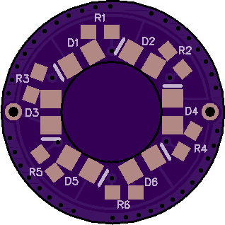
There is no parts list, I will sell those for a fair price
I spend a lot time to make it work that way and designing the boards
I will make them with a max current and option for 2 potentiometers that can tune about 30-100%

The boards are the easy part, tuning the LEDs was quite time consuming

Biggest thing is you literally need for each LED and each max current of the bord different values
I measured this to find the right values that took a lot time

The LEDs are from various chineese shops and likely not all the same
of course if you do not get the same LEDs the resistor values wont match

First I tried it on my regular 6x tail boards with conventional 6 Balance resistors and a 1kOhm Bleeder
Main Problem was that with low battery voltage the higher voltage LEds (Blue, White, pink, ice blue) get dimmer tan the low voltage ones (red, yellow, green)

I came up to enhance this idea with a voltage regulator, but had to do some steps to make it work

first get the voltage and resistor value for each LED at the same brightness

Then I made some calculation to get fixed current draw versions
But when I made the prototypes I saw that this is pointing in the right direction
but a lot manual changes were needed to equal them out on different board currents

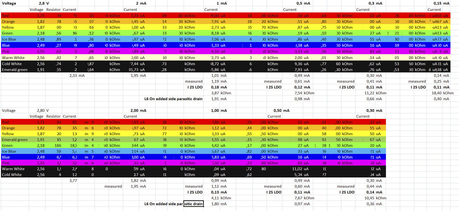
It is also possible to use this with side switch lights like Convoy L6, as I can get the parasitic drain for the 18kOhm bleeder down to 0.4mA when the tail board has 0.15mA for the LEDs

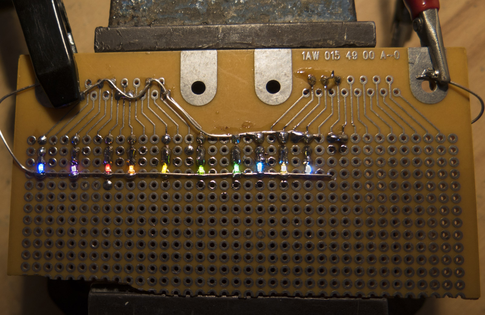
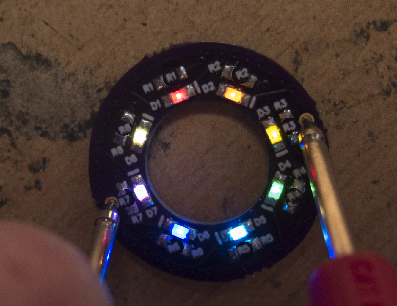
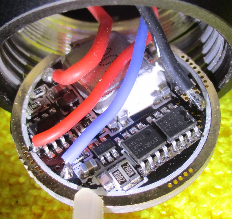
Now the first 4 Prototypes
I did quite some measurements and tests to even out the brighteness of them
Firt L6/L2 prototypes are build and successfully tested on my bench, modding the lights will follow

One tme i skipped the very current hungry Emerald green for a warm white

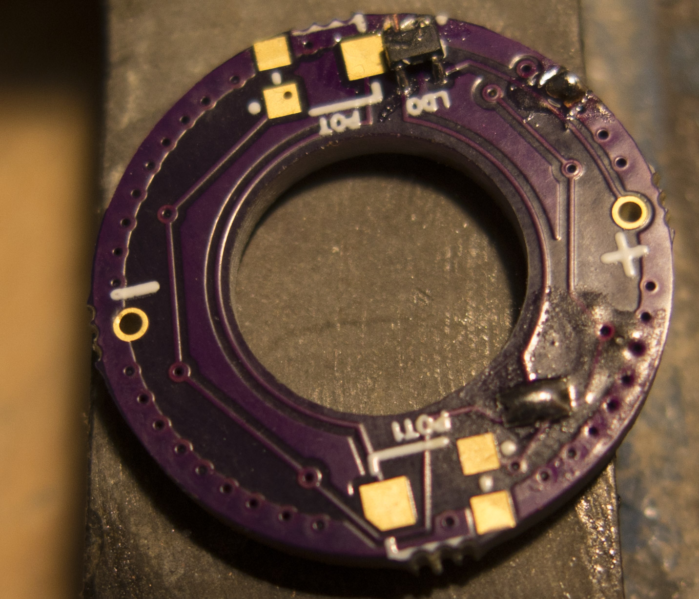
The tail board itself uses a voltage regulator so the brightness is constant down to 3V cell voltage and can be fitted with 1S or 2S voltage regulator
The 2S Voltage regulator has a 0.1mA higher drain

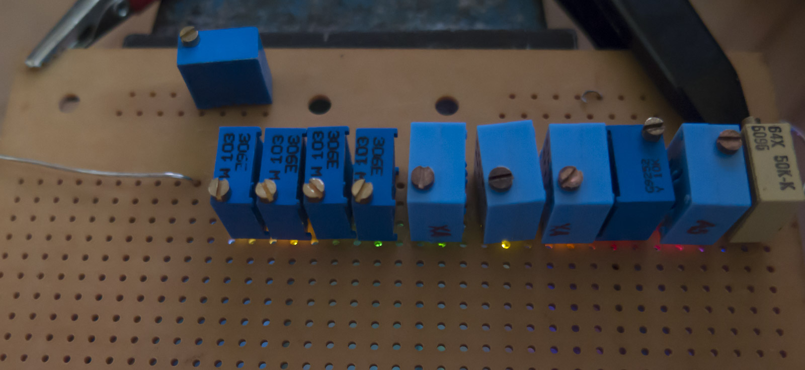
I haver also ordered fitting 3x3mm trimmers so that the brightness of the board can be adjusted for 2V and 2.5V LEds in 2 groups
On the other hand I can also build em with a current draw from 0.15-1mA with the balance resistors without trimmers

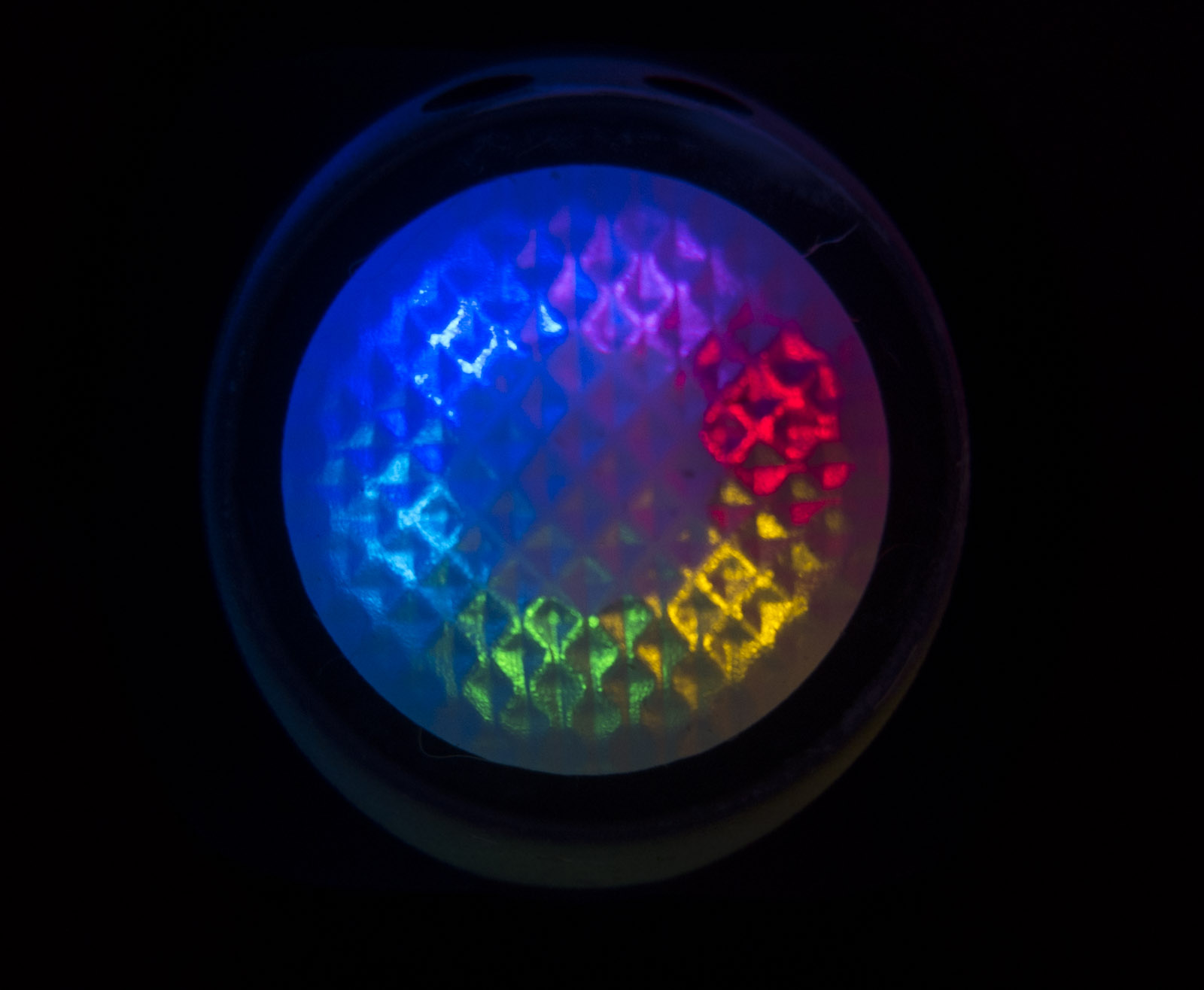
The rainbow LED boards have one drawback which are the inefficient Emerald green and yellow LEDs,
so their brightness is lower than green or white LEDs at the same current

The LEDs are all measured by me and trimmed to equal brightness
The thing is adding the tail cap cover I also saw some colors do not get equally through it, so again minor changes were needed

Lexel, after reading your post, I think I can confirm that I am still in the dark ages when it comes to electronics. You sure put a lot of research and work into this project to make it work, hats off to you.

The simple Layout without a voltage regulator is shared on oshpark

Those work great with 2-3 colors that have about the same LED voltage or you will see one LED type getting dimmer with droping cell voltage

you can find them here as well a lot other shared stuff

The ones with balance resistors for each LED are better

Here is the driver. I don't see anything out of the ordinary as to why the light doesn't work?

BTW, I unscrewed the star with the LED on it thinking I need it to expose the driver more. Now I know I did not need to do that.

Anyway, the star came off the heat sink with some silvery grey powder residue. I assume I need this paste before putting

the star back on?

Good the Leads and switch wires are still attached, I have had LED leads/Switch wires either break or come loose due to cold solder joints.Can you hook up a 2S 8.4v battery set up to the driver and see if it works, now the driver is clear.

I probably could but I don't know how

I have a quite a few good 18650 Laptop pulls so I soldered 2 in series and then soldered leads to the ends for quick portable Brewster Projects home boy testing. :smiley:

I like your setup, good old fashion engineering 
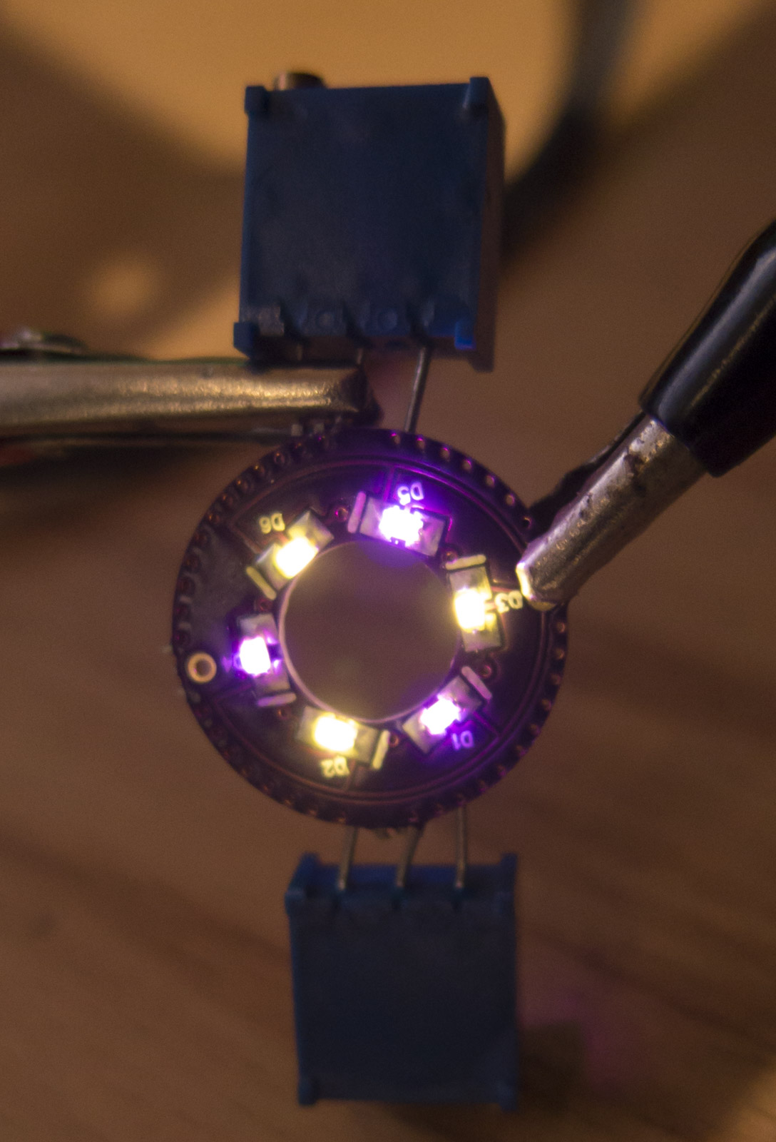
Is there any easier way for me to test the driver though?

You could ring it out with a DMM, check for ground short, ground ring on the driver to the driver spring. E-switch should/could blip once, but if it is truly grounded out will continue to ring.

The battery/power set-up is just easier to check the whole set-up. You can remove the leads from the star and check the LED off the battery set-up too. Just don’t over heat the LED it’s going to get HOT real fast!

Ok, I will run a few tests and see if I can figure out what is going on there. I'm going to watch a few how to youtube vids first just to make sure I know what I am doing.

I touched the LED + and - terminals briefly with a little 9v battery that I wired up and the L6 led lights up, so I don't think there is anything left except that the driver died for no reason unless anyone else has any ideas? BTW what paste is recommended to use to mount the the star on the heat sink?

Try to jiggle all the components of the driver to see if anything has be unsoldered from its pad.
Also set your multimeter in Ohms and check the resistance between the power wires.

I did jiggle everything but except for the spring bypass wire which disconnected from the spring it looks good. I unsoldered the star as I want to replace the driver since I have a spare but the side switch which is connected to the driver by two wires only goes out from the front. Does that mean I have to unsolder the side switch wires as well? The joints are so tiny on the switch, it wouldn't be easy. Is there another way?

You can either file tiny notches as seen here or file the sides of the switch pcb flat. Both work.

Very helpful thanks. Got to go to the hardware store now and see if I can find such a tiny file as I like the idea of filing the head in case I do future mods.

The top and bottom of the hole are thinnest and are easy to open up. The sides are much thicker.

Thanks for the tip. Just getting at it now so that really helps.

Got the new driver in and it works now, but it stays on turbo and the side switch does not work, only the tail cap switch works?

Update: I found the problem and got it working. I see now that the old driver would have been fine too and I did not need to swap it but at least I know how to do it now. The problem was that on my functioning L6's, there is a white round plastic ring around the emitter to keep the reflector high enough not to touch the contacts. My one is missing the white ring and that explains the on and off problems with this one. I pulled off the reflector and everything works. I put it back on and it goes haywire. I need to somehow find that ring and if I'm lucky Simon may have one.