After following a couple of threads on voltage references, I thought that perhaps I could find one already inside of a Digital Volt Meter.
How else could they work i thought. There must be some sort of reference voltage already in there that is used to compare against.
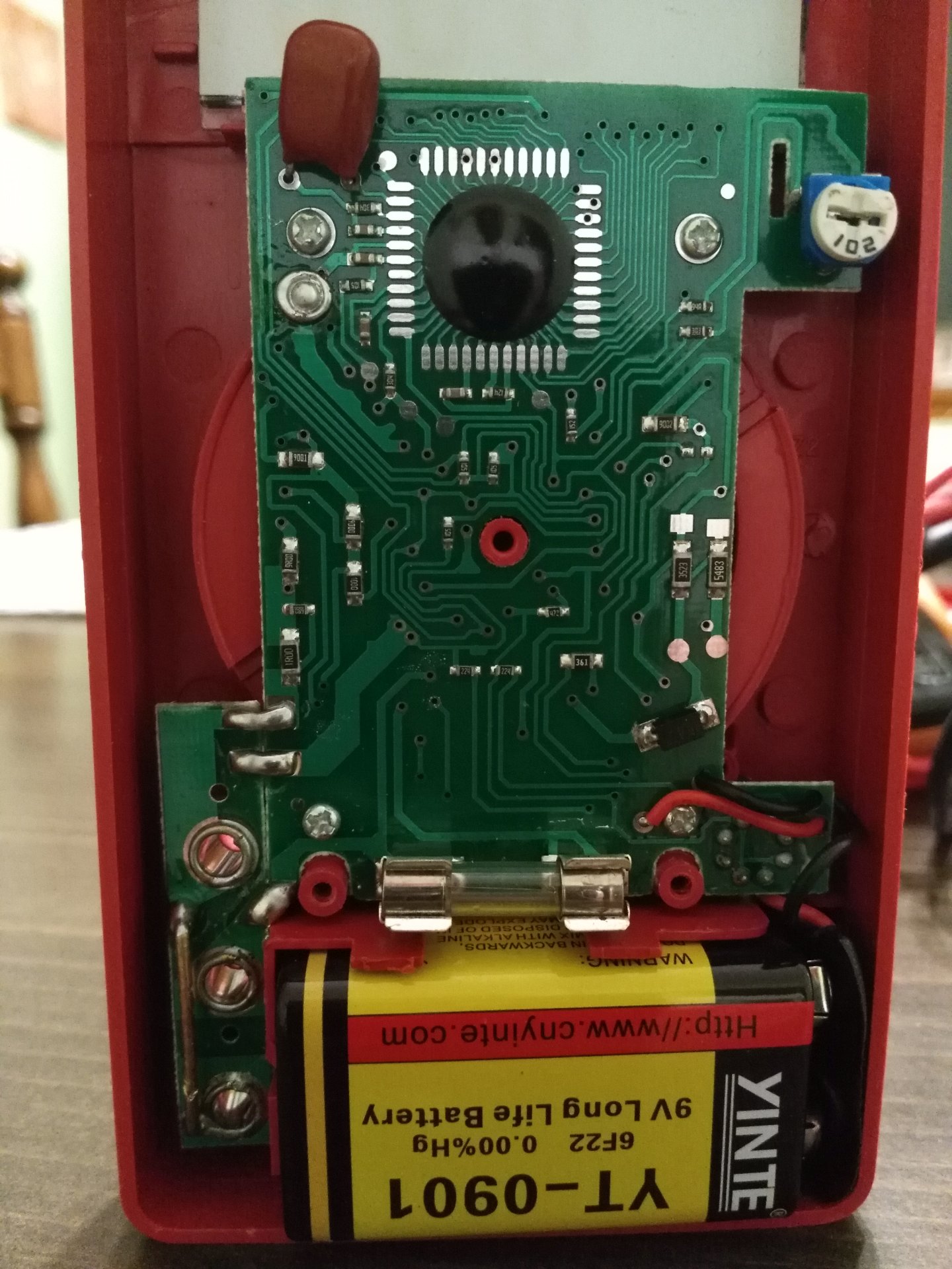
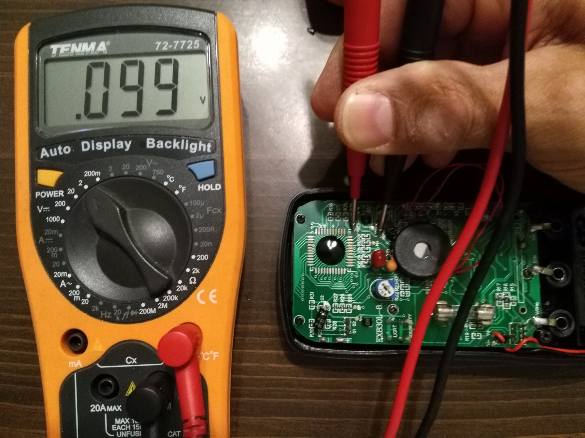
So I opened one up, here is what I saw.
In the left picture, the red arrow points to the trim pot that is used to globally adjust the meter. That is it adjusts ALL scales at the same time, probably not the most elegant way to do it. The blue arrow points to the COB (chip on board) that is the brains of the DMM. If there was an onboard voltage reference, it would be produced inside that chip, at least that is what I thought.
AND, if there is, I would think that it would somehow be connected to that trim pot. So I followed a trace from the trim pot over to the COB. The picture on the right shows that trace in red. And it includes a solder pad! A good sign?
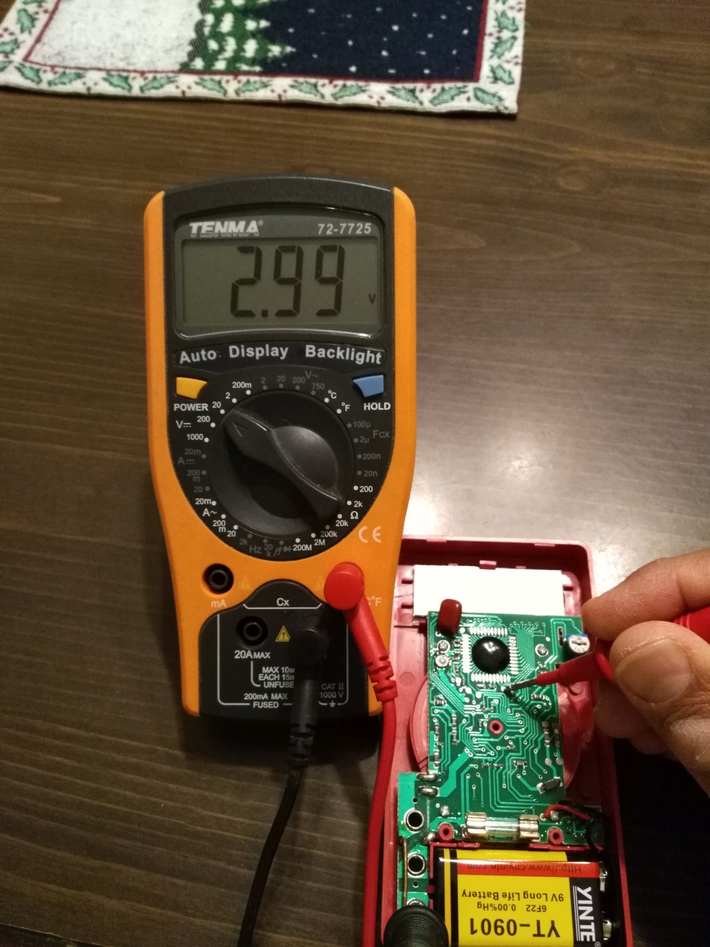
So I used another meter to measure the voltage from the solder pad to ground. “2.99V” I thought that to be an indication that it IS a 3V reference voltage used by the DMM.
So I soldered wires from that pad and ground and connected them to 2 screws that I installed at the top of the meter.
So after this mod, this meter is still fully functional. Those 2 screws are my “reference” 3 volts whenever I want to check another meter. How accurate is that 3V reference? I don’t know for sure, but I think it exceeds the calibration of any of the meters I have. In other words, I think I can use it to calibrate other meters.
BTW, I opened up a number of other brand meters that I have. I could not find a reference voltage in any of them.
Only this, and other, free Harbor Freight meter had this feature.
How solid is that 3V reference? Pretty solid, I’ll explain later.
And I am calling it a 3V reference rather than a 3.xxV reference because I just don’t know how accurate it is. I can tell you that all 3 HF meters I checked, using the same meter to measure, all produced exactly 2.99V
One of the mantras here is that if your DMM starts giving you crazy readings, check the battery.
It’s true, and I have experienced it myself. For some reason, some meters when their battery gets low, start giving erroneous readings. Most meters I have seen have low battery indicators, but I have seen this effect before the warning
Based upon the first post, I thought that perhaps as the battery inside the DMM runs down, the reference voltage couldn’t be maintained.
That could explain the effect.
Wouldn’t it be stupid for a manufacturer to allow a DMM to still function past it’s ability to maintain that reference voltage? It seemed to me that they should design it so that the display shuts off before the reference voltage changes due to a low battery.
So I thought I would test for that.
I removed the 9V battery from the DMM I modded and used a variable power supply to power it.
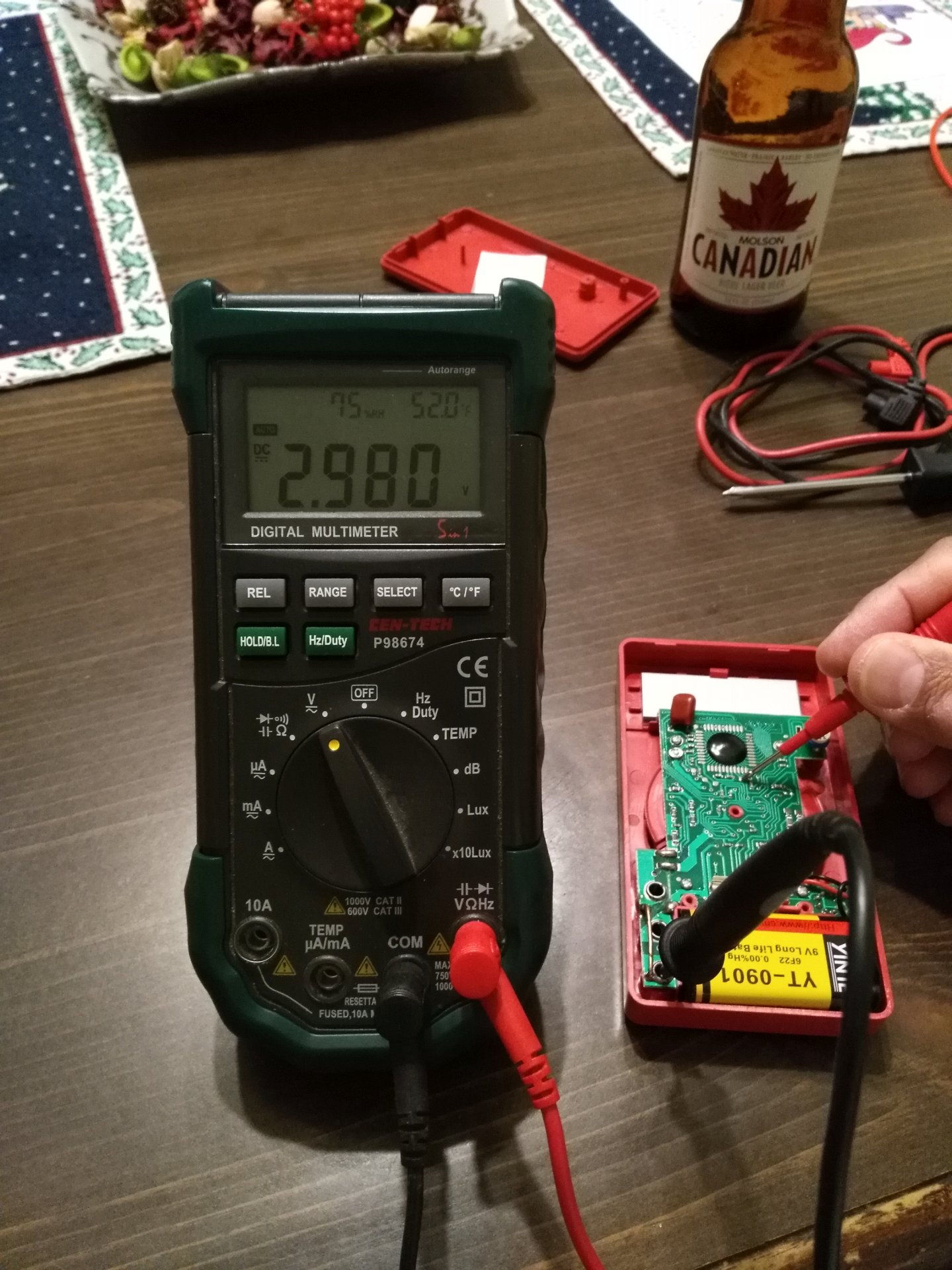
This first picture shows the power supply on top and 2 meters on the bottom. The meter on the left is the modded DMM and it is connected to the meter on the right which is measuring it’s reference voltage (2.99V)
The modded meter is also connected to the 9V battery that was removed from it. I realized now that I had the leads crossed and it reads –9.79V What I want to do is slowly lower the voltage from the power supply and see what effect it has on the reference voltage AND the voltage reading of the original removed 9V battery Power supply voltage at 9.81V Power supply voltage at 7.02V
This represents a significantly rundown 9V battery. The low battery indicator on the meter display has not yet turned on and both the reference voltage AND the measured voltage of the battery remains constant! Power supply voltage at 6.32V This is when the low battery indicator first turns on. Reference voltage and measured voltage are still the same :+1: Power supply voltage at 6.02V Everything is still holding steady. Blue arrow points to low battery indicator Power supply voltage at 5.02V Everything is still holding steady.
Anything lower than this causes the display to bounce around with different readings.
However, even at that low voltage the reference voltage held steady!
I don’t know why I couldn’t reproduce the erroneous readings when input voltage was lowered, but I was pleased with the results of the reference voltage
Wowwwwwwwwww!!!
ImA, in an instant you blew up my world
But, it was only temporary
Fortunately It does not change the “reference” voltage. Of course if it did, it would mean that the 3V would have been manufactured by the trim pot and not the other way around.
I never even thought of that.
Just an FYI
I dug deep into my stash of meters and found a model different from the others. It was old enough that the preinstalled battery was dead.
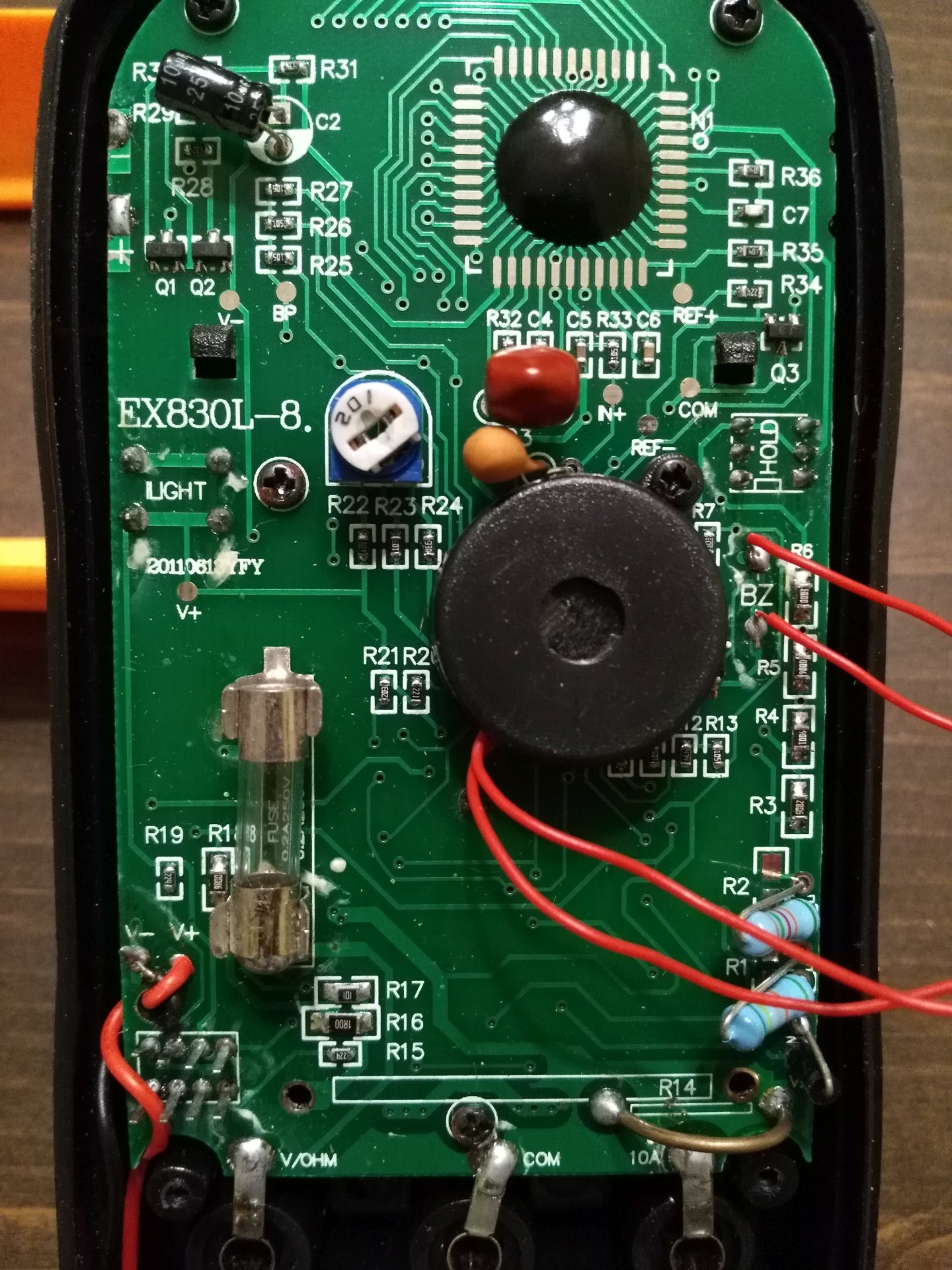
The circuit board looks different from the others I am currently using, but functionally it appears to be the same.
There is no solder pad on the back side of the board and the COB is rotated 90 degrees anticlockwise on the circuit board.
Whereas the reference point off the chip is the 4th from the right on the bottom row, on this board it is the 4th from the top on the right most column.
I measured the voltage of all these DMM’s and they varied between 2.97V and 3.01V with nearly equal distribution.
My take on this is that it is not a high precision reference. (that’s why there is the pot). From what I have read about the chip. the Intersil ICL7106, it is probably not the reference voltage created inside the chip. I suspect that voltage to be actually lower, probably in the vicinity of 1.2V. Also that ICL7106 can optionally use an external voltage reference such as the ICL8069 mentioned by HKJ.
Also while researching, I found something that I thought was VERY interesting. The ICL7106, the very first “DMM on a chip” complete with drivers for LCD displays, was originally developed jointly by Intersil and FLUKE for a line of 3 1/2 digit DMM’s. It was the first meter to use a “DMM on a chip”. Intersil later made a few changes to the design and released it on their own.
FLUKE sued.
Later FLUKE developed a 4 1/2 digit chip on their own. That ICL7106 is now used by many, many manufacturers of cheap DMM’s and the chip itself has been cloned over and over.
Here’s what I came up with. I only had one of these HF DMM’s at home to open up and it looks like DCH’s first one:
Measuring with my Tenma DMM (the meter I use the most):
Measuring with my Harbor Freight Mastech MS8229 clone:
And just for the heck of it, measuring with a $6 XL830L (this meter is junk! probe receptacles fell apart when I put the leads in to do this):
Then I decided to open up the XL830L:
Notice the “REF+” and “REF-” spots? I then measured across those with my Tenma DMM:
Measuring from ground to either one of those spots gave no reading.
Then when I got back to work this morning, I measured that same HF meter with my new ANENG AN8008:
I’m not sure which DMM is most accurate. I always assumed the HF MS8229 clone was (came highly recommended by PilotPTK way back when). My Tenma has always been very close to agreeing with that one. The Tenma definitely feels the highest quality of all the DMM’s I have. The ANENG does feel like pretty good quality too, way superior to that XL830L! Oh, and I also modded my HF MS8229 clone a few months ago. I got sick and tired of the probes being pushed back up out of the receptacles and therefore making sloppy contact. My mod got rid of the spring tension, yet maintained the function of the jack lights and beeper (beeps & flashes when your probe isn’t in the right jack - not that I care about that, I just wanted the beeping to stop).
The first, second, third, and forth DMM's pictured below are model numbers 98025, 90899, 98025, and 98025, respectively. Not sure the model numbers on the cases matter though because the PCB differ in the 98025's. They measured 2.97-2.98v, 2.97-2.98v, 2.99-3.00v, and 2.98-2.99v, respectively.
Thanks for checking guys.
So the range of measured voltages seems to be tween 2.97 and 3.01. (I measured a couple of non HF meters)
2.99V would be the median, so they vary by + or - 0.02V.
That works out to + or - 0.67%, not exactly high precision.
However if I choose to use the median value of the one I built, which was 2.99V, then there is a good chance it is closer to what I believe to be the intended voltage of 3.00V
So for now I will use the meter I modded and “call” it 3.00V.
I think that even the hardest skeptic could agree that it is at least useful for checking a meter to make sure that it isn’t way off.
ImA, did you ever get a voltage reference? If you did, how does that 2.99V compare?
Now here’s a question
Suppose I go out a buy a precision voltage reference board. How do I KNOW it’s accurate? LOL
I did buy a reference a while ago. I don't know if it is indeed accurate, but I have no reason to not trust it. I haven't calibrated any of my DMM's with it yet though. Each one I opened either had multiple trim pots (Didn't know what one to adjust) or no trim pots. So I just marked what they read at reference to help me guesstimate what the reading should actually be. I noticed one of the meters above has a trim pot. I will attempt to calibrate that one and then measure the DMM's.
I would like to say that my readings should be taken with a grain of salt. I measured with one of the above HF meters for three of the meters and another one of the above DMM's for the remaining DMM. Stock leads. So there could be variability in my measurements due to potential issues with the leads. Most of the stock leads I have opened up have really lousy connections. I didn't use my favorite meter because it's battery was dead and I didn't have time to rectify that last night.
I'm pretty excited about the built in references. Will be nice to always have a reference available right on the DMM's. I don't need high accuracy for most of my stuff.
I was in a Harbor Freight today and noticed that there has been a change in the “free” DMM’s that they have for sale.
The first thing I noticed was that the packaging was different and they are no longer the “CEN-TECH” brand. This store had a mix of the old and new still on the pegboards.
Of course I happened to have a coupon for a “free” one with any purchase, to I took one. Once I got it home and unpackaged it I noticed a few other changes as well.
The maximum readings on the higher AC, DC volts has been lowered and the maximum current reading has been lowered from 10A to 5A.
I suspected these changes were due to safety concerns and didn’t reflect what the meter would actually read up to. To test that, I passed better than 5A throught the new meter and it read it correctly. I didn’t have a source of high voltage so I couldn’t test those ranges. (I never had reason to measure those higher voltages anyway)
I opened it up to see what differences there were inside, and it looks like a new design. Over the years I have seen it change before, but this one has a couple of important changes.
First, it is apparent that the gauge of the shunt resistor has been increased. (smaller wire). So it really is only able to pass 5A.
Also there is now no pot to calibrate the meter. I compared it to others and it generally seems to be calibrated as well as others.
The pad with the reference voltage is still there and this one puts out the same 2.99V as most of my others, so at least that is still the same.