the fet board is very interesting, i always have problem with the durability of clicky switch in convoy s2+( and more other lights)
This is very interesting, thanks for sharing!
Cool stuff :+1:
This will be especially interesting to the hard-core modders, like Dale, who are always squeezing a little more performance out of their lights.
:+1: ![]()
What kind of battery/supercap do you use?
I would use a LFPAK33 Mosfet
Apologies for my ignorance and I'm not sure who Dale and Everett are, but hopefully the GFS system will be useful for anyone looking to try some new things on their lights ^_^/
Anyway I've been using this new switch system for a little bit and it's been working really nicely so far. I'd imagine people who like to use DD FET drivers might find this useful to squeeze out more performance.
Sure the LFPAK33 is a fine package. IIRC it's used on a lot of smaller FET boards as well as those used in the LED4power boards. However I saw no reason to since space is really not a constraint, and the Powerpak fets are generally more robust, with a lot more options available from different manufacturers with comparable or cheaper costs, and definitely much better R_ds_on at low voltage gate drives  . I suppose if I used one of those fat springs http://www.mtnelectronics.com/index.php?route=product/product&product_id=385&search=spring I could put a smaller FET in the middle. Maybe I'll just make a board with dual footprints and everyone will be happy!
[Edit]
Ok I had half an hour to mess around and I've made a Rev B with dual footprints. 
OSHPark board here if you want to order: https://oshpark.com/shared_projects/dwoKK9Uo
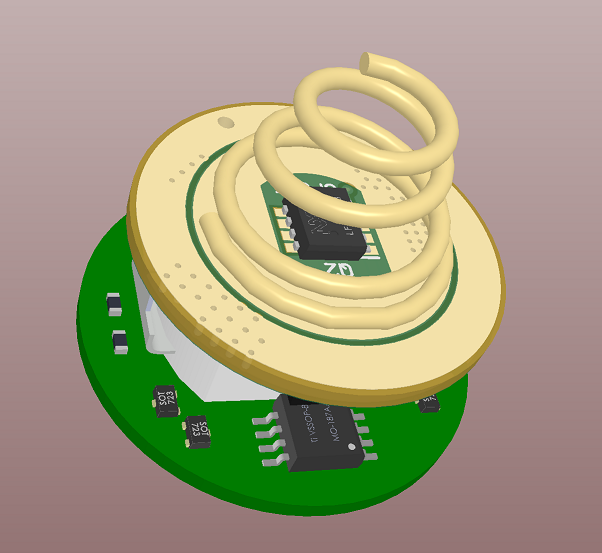
Here's how it should look like!
Won't fit small springs but I guess if you're serious about modding, you'll have a few of these lying around: http://www.mtnelectronics.com/index.php?route=product/product&product_id=385&search=spring. So now you can use whatever FET you want . Personally though for my builds I'm just going to stick with the PowerPak SO8 just because the FETs are strictly superior, especially at low gate drive voltages
Happy weekend everyone!
Yes, it should be useful to anyone wishing to add lighted tailswitch. I was just saying that the hard core modders will be the most likely to jump in early, because they’ve already squeezed out maximum performance in every other area possible. Dale is BLF member DB Custom. He has made some insane builds, including getting his titanium neck light to output over 1000lm using just a 10440 cell for power.
Sub’ed.
Loneoceans, you’ve got mad skills. I’m glad you found our forum!
I’ve built a bunch of the basic illuminated tailcaps, would love to build a couple of these bad boys. I’ve soldered quite a few 0805 LEDs by hand (what size did you use?), but those resistors look absolutely TINY.
Hello GChart, thanks for your kind commends! The LEDs I used are 0603 size and the resistors are 0402 size. I recommend these Wurth Electronic LEDs, only because they have a nice triangle marking on the bottom telling you which is the anode and which is the cathode. However you can use any other size you want.
I made them small so I could fit them properly in a ring with sufficient clearance around them. For example in the Convoy S2+, the LED ring replaces the metal washer which the switch sits on, which then presses against the shelf. For some of the other LED rings out there, it appears that the resistors are placed in this keepout area so you'll be crushing the resistors, which should work fine, but is bad practice (e.g. the end caps of the resistor can crack from the substrate etc).
As for soldering, if you can solder 0805, you can solder 0402. If you find it too difficult, it's actually more a matter of using the right tools and solder. I highly recommend using a fine tip soldering iron (actually this is not that critical), needle tweezers (critical, and cheap), and the thinnest solder wire you can find (VERY important - use .015"/.38mm or 0.020"/.5mm solder). This will make your life so much easier.
Also magnification helps, either with an optical setup, or with a USB microscope or your phone (there are apps that do this!).
I’ve been using the PilotDog68 Rev5.3 boards (top only; not using the bottom/pot boards). The LEDs seem to have sufficient clearance, and the resistors are located on the bottom of the PCB so as not to be crushed (link)
I’ve found that when working with some of these small buggers, it’s easier to put a dab of solder paste on the PCB pads, place the components, and then just touch the connects with a small/chisel tip iron. Not sure if that’s proper, but it works well for me.
Looking forward to that BOM ![]()
Mad skills sounds about right. ![]() Nice work. :+1:
Nice work. :+1:
Nicely done, I might have to put one these together
Hello all,
Thanks everyone again for your kind comments. I managed to put together another set of FET tailswitches with the smaller form-factor FETs and nice Beryllium Copper springs from Noctigon and it's working beautifully.
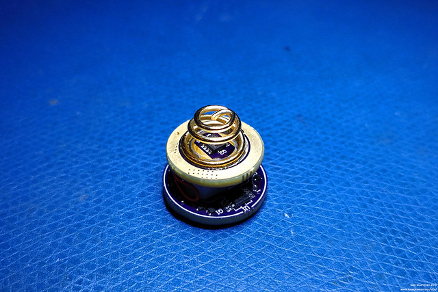
All fits well (in a Convoy S2+).
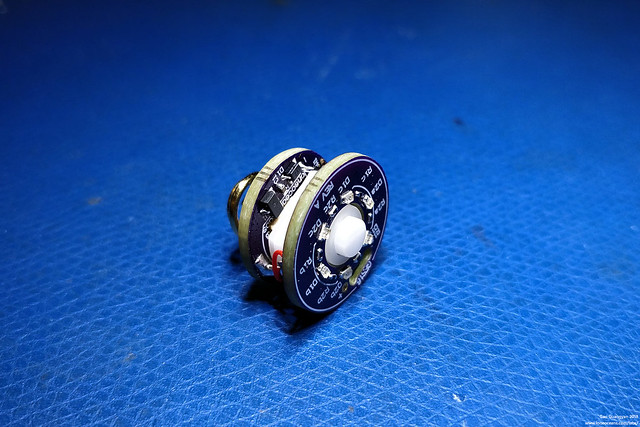
An alternative view.
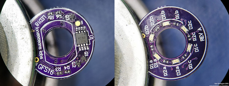 Finally, above is a clear view of the GFS16 (LED 18mm) board with components soldered as a reference for people trying to make their own. The BOM is updated in the OP. With the default resistor values, BANK 1 of LEDs turn on when V_bat is >2.97V, and changes to BANK 2 when 2.73<V_BAT<2.97V.
Nice! Thanks for sharing.
Damn I wish I could solder small stuff ’cause I would love one or two of these :heart_eyes:
Small stuff indeed. Amazing work. ![]()
Great! I have been waiting for years for this! A guy on CPF used to offer these, but with forward clickies and completely over-the-top prices.
Hello all, 1st I want to thank loneoceans for sharing this with us. just finished building 2 switches and they work with the H17F driver only if a bleeder resistor is added, I used 2.2Kohms and all functions flawlessly. My question to loneoceans or anyone who may know... would a lower value bleeder expedite the coin battery charging time.. with the 2.2Kohms it took about 3HRs off time to charge from 2.55v to 2.67v on a full 18650 battery, Thanks.
![img]https://i.imgur.com/64TojtG.jpg[/img]!
![img]https://i.imgur.com/bSa23Fr.jpg[/img]!
![img]https://i.imgur.com/eugZNBC.jpg[/img]!
![img]https://i.imgur.com/Q1uZNvW.jpg[/img]!
![img]https://i.imgur.com/N5EzwVN.jpg?1[/img]!
2.2Kohms bleeder is only good for the switch board alone, for both the switch and the led board... 3x 2.2Kohms or 733ohms worked perfectly.