Would the momentary in your remote FET switches be the same as having an e-switch tail?
The reason I ask is because if it does, then it’s only a step away from mounting an e-switch in the tail instead of having the remote pad.
I recently got a few budget lights with e-tail switches (whole driver in the tail) and really like those switches.
So I’ve been toying with the idea of converting a light to an e-tail switch with the driver in the head.
One method is with the tailcap FET circuit, which requires a small battery or capacitor in the tail (like the Ti Tool)
Although personally I’m looking at method #4 (driver in the head) with e-switch firmware.
From my understanding the FW3A uses method #4. I think it’s kinda hard to retro fit that method to existing lights. I wish to modify some edc’s like my D25C, there is nothing wrong with the stock switch but for waking in the night I prefer a (near) silent switch.
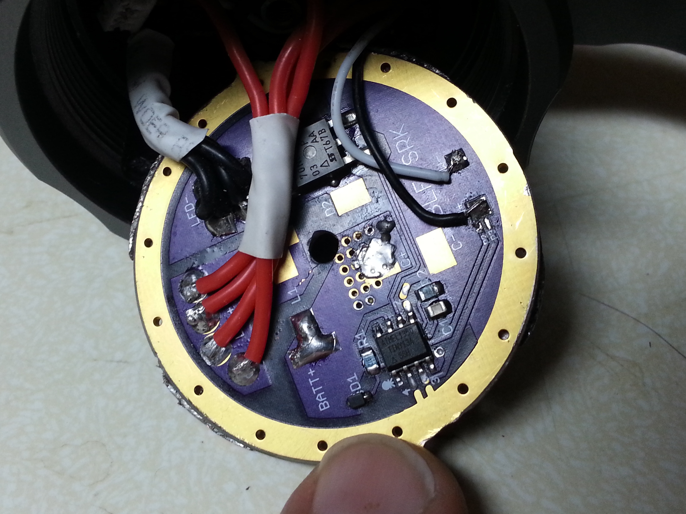
The remote fet switches are only momentary action, meaning - push = light on / release = light off
The ti tool switch is what I want but it doesn’t need to be that small.
The Bistro are working, but I got still some glow between blinks,
to address this a new board need to be made for NarsilM drivers as they do not shut down completely including firmware change which I am not capable of
The people I asked to change Narsil do not respond
.
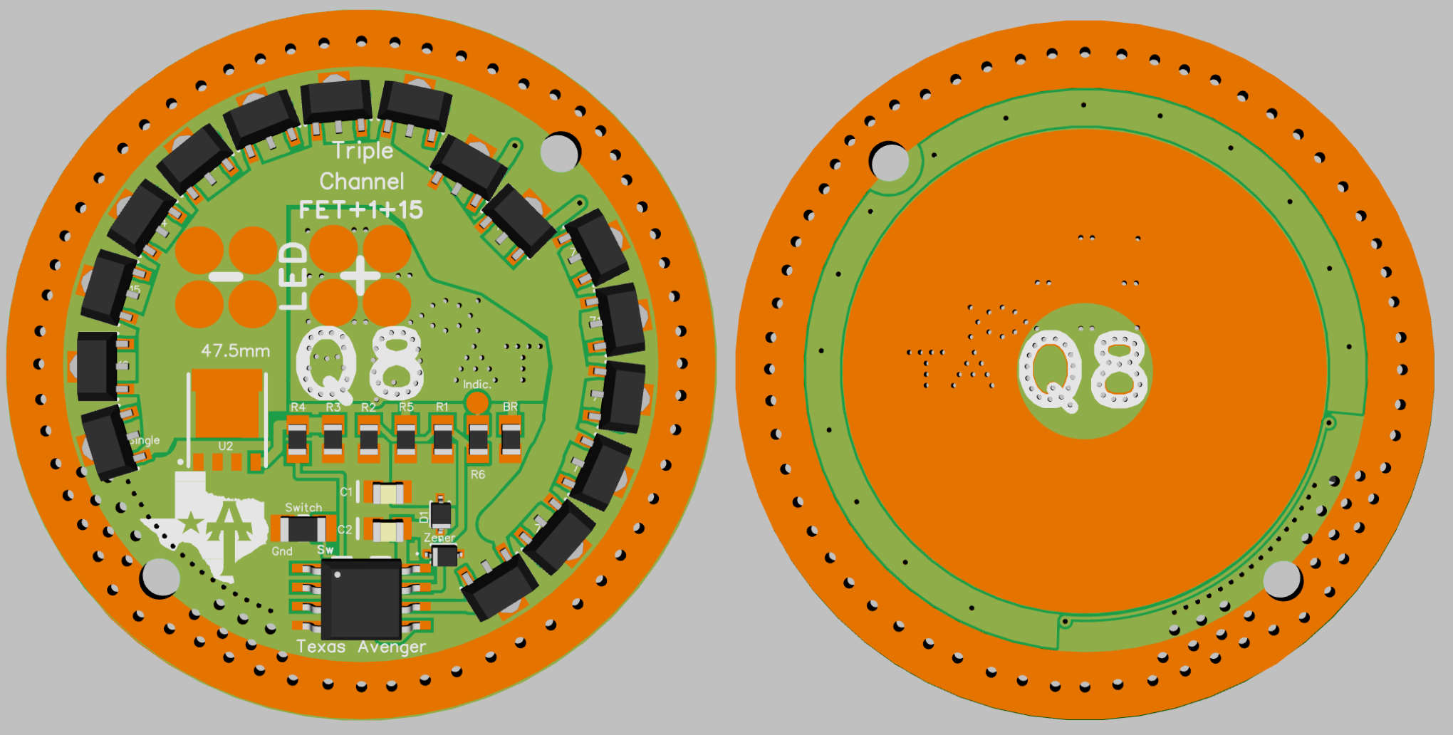
I’m looking at the Q8 driver (4p) for a blackshadow terminator. The stock driver is 47.5mm diameter. It appears it will work, has anyone tried this?
The BST has a lighted e-switch (4 wires) would this be compatible?
Is there room to drill a small hole in the center of the board for the mounting screw? Like this:
Technically you can drill in the middle no parts or lanes there, but you have to remove the copper on both sides to prevent shorts from battery+ to ground
.
Thanks, assuming the green area has no copper… the mounting post under driver is 5mm and the nut (battery side) is 6mm, so the need to remove copper depends on how big is the area with “Q8” lettering in the center?
It will be much easier mounting to drill the center (if possible), but it may also be possible for me to use the 2 existing holes instead if I drill/tap two new holes underneath and find long enough screws, what is the diameter of the existing 2 holes?
Also, how thick is the board? And is the battery + contact ring thicker and stand out from the board? The BST stock board is 2.25mm thick and the batt + ring stands out another 1.75mm for about 4mm total height from the mounting lip to the + contact of the cells.
,
I assume this is compatible with a lighted e-switch? My switch has 4 wires, so I guess 2 are for the LEDs
Yes, but the Q8 driver only controls a single switch led circuit. It can’t do two independent colors.
Typically 4 wire switches can be a single common wire (common ground or common positive), one wire for the switch and the other 2 wires control 2 different color switch leds. Polarity on the switch wires is important to make the switch leds work.
the whole middle area on both sides has positive battery + copper, insulating it is nessesary or remove copper
batt+ can be used with a resistor for one LEd color permanent lit the other MCU controlled
driver is 1,6mm thick and has no stock brass ring, you need to solder it from one to the other driver with hot air
the thickness can be increased using 3 spots on the ground ring with solder blobs, or some other material like a copper wire in between head and driver