Beamo, certainly try the irons first if you gave some that are untinned. It’s hard to get heat transfer through an untinned tip, but since you have so much power it might work.
I’ve got this #312 pen and it works great. I really don’t know much about all these different flux formulas and such. What you linked to might be fine as well. All I can say is that adding a little extra flux makes a huge difference in getting really nice soldered joints.
I think Lexels big heat gun technique is pretty advanced and not what I would recommend for the first time. Maybe it would be good as a last resort if your big irons or small torches couldn’t get it hot enough to melt the solder.
There’s really no need in heating the entire driver because as soon as the solder liquefies, that thin copper layer on the driver is going to almost instantly get up to the proper temperature.
Ok, yeah that does make sense, but I wonder if I should have him build one with the glue anyhow, just in case.
I would have to imagine the 250w or 300w iron would get it plenty hot pretty quick, I’ll try that for removing the ring from the old board and see how quickly it de-solders it.
I think I’d be more comfortable using an iron than the torch, but I did have a thought of pre heating the ring with the torch immediately before I set it on the board, then rest the iron on it, just to help get it up to temp quickly.
There is a possibility I’d get the reflow station before I attempt this, I assume the reason hot air is best is because it can more quickly heat up a larger area or component like this? And with that small air gun there wouldn’t be the risk of de-soldering any topside components?
Wow, you’re awesome! Thanks for posting these photos! It’s nice to be able to enlarge them, I’m stoked about this driver!
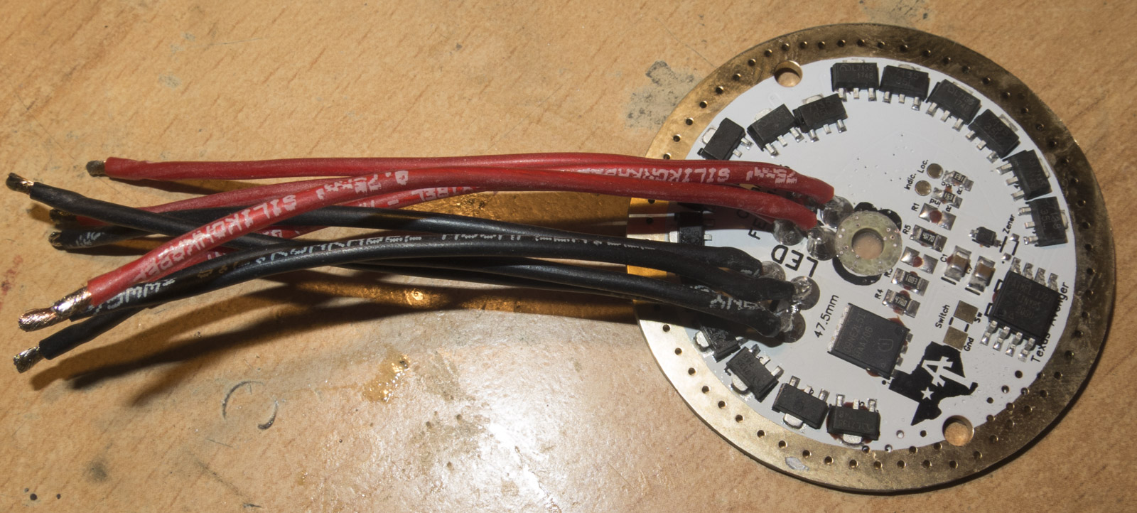
So the wires are 0.75mm² ? I looked up the conversion to AWG and it looks like that’s equivalent to 18ga. (which is good I wouldn’t want anything bigger)
Just to confirm: ramping max at about 80% is current regulated/mixed, double click turbo is 100% direct drive ?
For the UI:
It’s NarsilM v1.2, correct? What is “GT” v1.2 ?
Are these links correct for this?:
Also is there an active shortcut to toggle between ramping and mode set? or do you need to go into config to change it?
I super want to do this to my MF01 but have no clue in terms of where to start as I’m super new to modding. I have access to incredibly skilled solder persons at work and I’m mechanically inclined but other than that what would I need to be looking at?
Lexel how did you open a glued MF01? I managed to open the MF02 but my MF01 is very tough. I heated it with a hot air gun but everything is just slipping on the bezel.
Looks like mines is a V2, as I can see just two wires on the mcpcb. Looks a bit involved from the pictures in that thread, not really sure anymore lol…
If I understand well, the BLF Q8 driver, with NarsilM, LVP customization and a max temperature preset, the price if 17$, right? Without shipping of course.
I had a question about your boost driver. I think you said it can provide up to 6A with a 6v led like a xhp70.2. Does this mean it would be drawing 14 or 15 amps from a single 26650 battery?