Clamp meters magnetization, demagnetization and offset
Clamp meters has a offset when measuring DC current, this is due to a couple of factors:
-
Magnetic fields, like earths magnetic field, but can also be from other equipment and iron in the building
-
Offset in the preamplifier, any electronic DC amplifier has a small DC offset.
-
Magnetized clamp, this is what I will be looking on here.
I will be applying large current to the clamp meters and see if the offset and readout will change afterwards.
Contents:
Equipment
Demagnetization
Clamp meters for test
How much do clamp meters magnetize
Do it affect measurements
Conclusion
Notes
Equipment
For this I need some equipment and I do not have a DC or AC power supply with enough amperes. It would be fairly easy to make a high current AC supply: Add a few heavy gauge turns to a transformer and run it through the clamp, then I could use a variac to feed the transformer, but it would not solve the high DC current.
Another solution is to pass the wire multiple turns around the clamp, this works for both AC and DC:
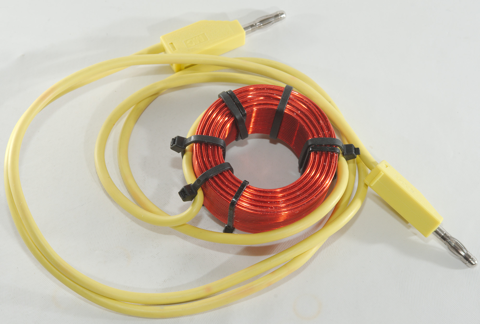
I have this coil with about 180 turns.
I.e. 1A through the coil will show about 180A on the clamp meter.
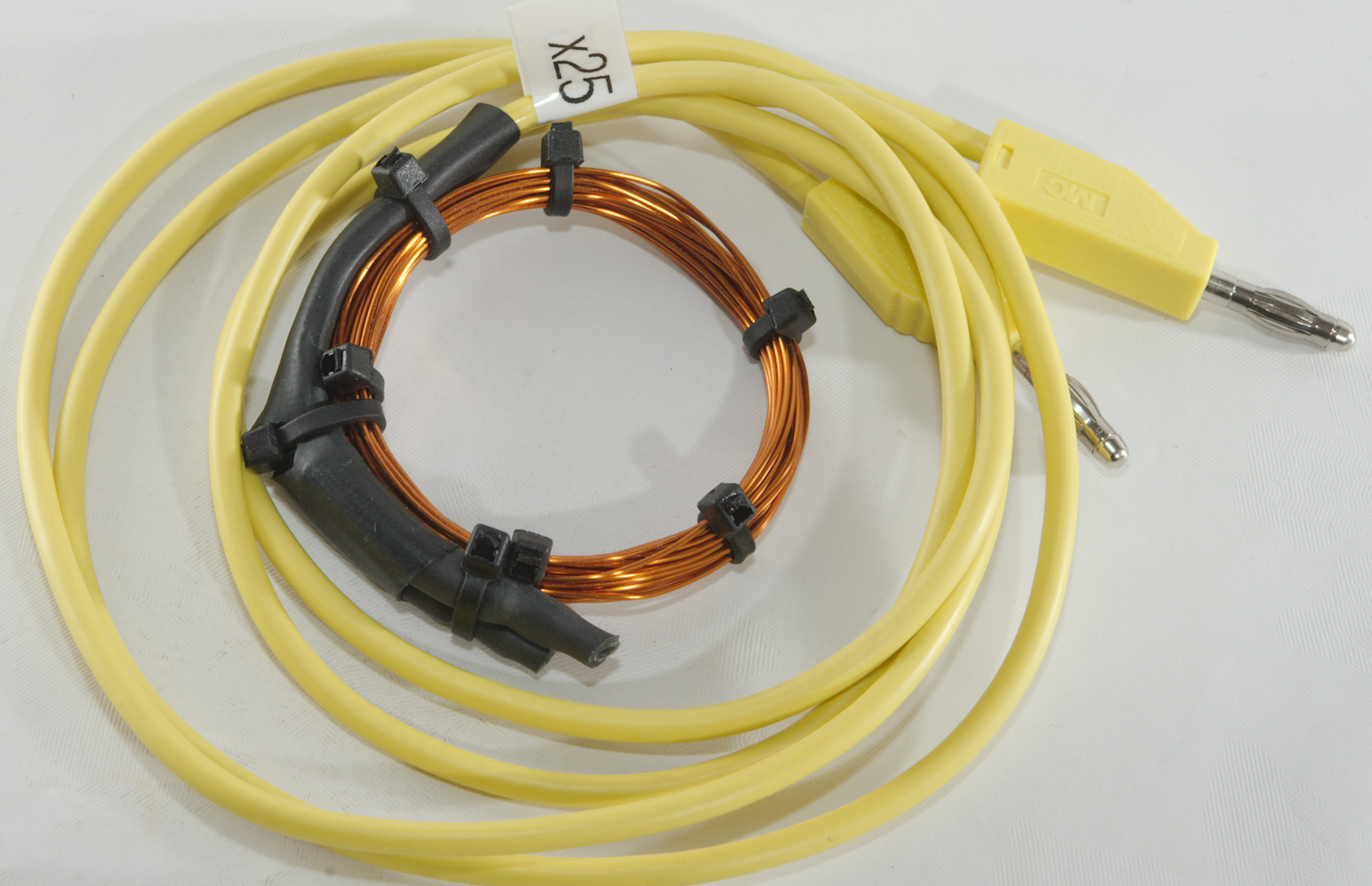
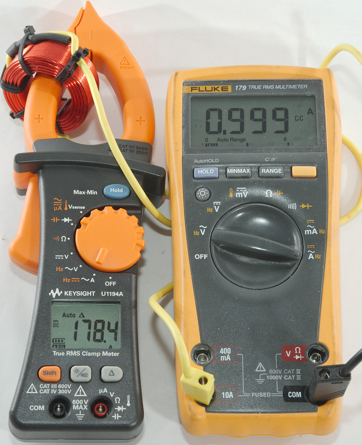
But 180 turns is too many when testing at 1A, the constant current mode in my power supply is a bit low on resolution for this. For that reason I made a 25 turn coil, with my standard power supply I can easily use it from 1A to 150A testing, that is 40mA to 6A through the coil.
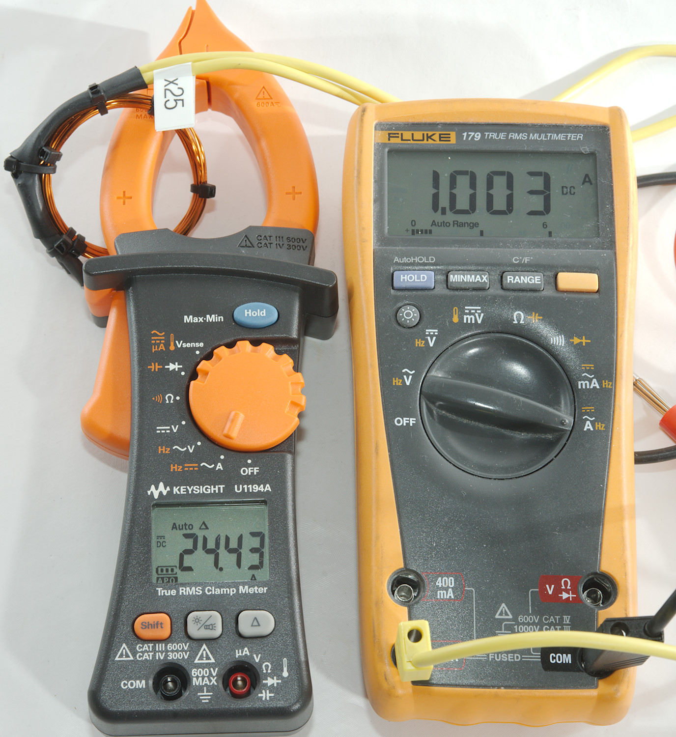
A test shows I did count correctly, 1A shows as 25A on the clamp.
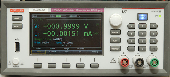
For power supply I have used my Keithley precision supply.
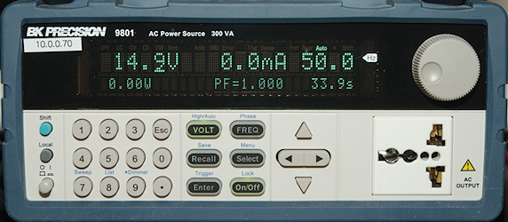
And for demagnetization I use my AC generator. This generator can supply from 0 to 300VAC, in this case here I only needed 25V and I put a 10ohm power resistor in series with the coil (The generator really dislikes highly inductive or capacity loads).
Demagnetization
Before most test I did a demagnetization of the clamps.
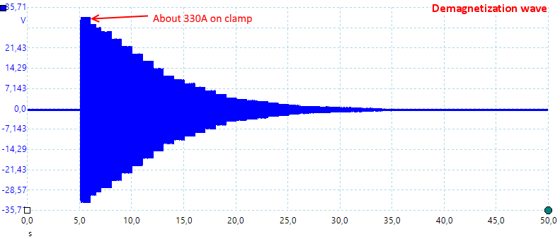
Using a computer to controlling the generator I could generate a fading AC voltage and supply that to the 180 turns coil, this gives a good demagnetization.
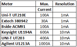
Clamp meters for test
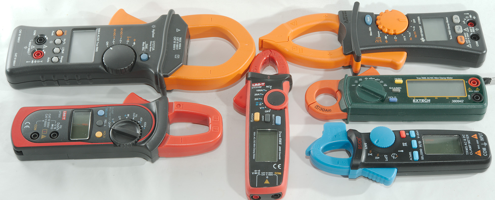
All my clamp meters with a claw large enough for both coils.
How much do clamp meters magnetize
To test this I used the 180 coil and simulated currents from 0.3A to 300A.
First I demagnetized the clamp, then I applied the different currents and read the offset on the meter between each current. Finally I demagnetized the clamp again and checked the offset a final time.
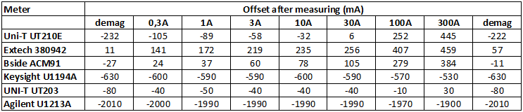
Some meters do magnetize and the offset values changes significantly.
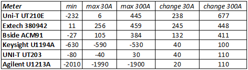
Here it is easier to see how much. The 3 meters with 1mA resolution is the ones that changes and it depends on current.
Do it affect measurements
Do this magnetization spoil the precision of the meter?
For this I started by demagnetizing the clamp, then measured 1A, 10A, then 1A again, 100A and 1A again, each time I was carefully zeroing the meter before each measurement. From above we know that a 100A measurement will add a significant offset to some meters.
Because I wanted fairly good precision I used the 25 turn coil for this.
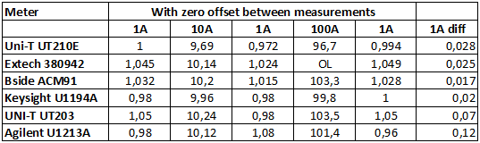
Comparing first and last column the difference is fairly small, i.e. the meter do not get affected significantly by the offset, as long as the REL/Zero button is used before measuring.
The UT203 and U1213A are not very stable at 1A, they are designed to work at higher currents.
Conclusion
The cheap high sensitive clamp meters will be magnetized and it will show up as an offset on the display, but as long as the zero button is used, it will not affect the measurements.
Notes
This test only goes up to 300A, higher current may magnetize the high current clamps.
Review of BSide ACM91
Review of UNI-T UT210E
Multimeters and current measurements