Cool! It’s fun to do stuff like this for the learning experience. Also, it’s always good to have more options available. ![]()
This is cool, very well done. I also really enjoy building and playing with these lighted tailcaps and your options are a very welcome addition. I’ve gotten pretty quick at hot-surface-reflowing the 6 LEDs on one side, then flipping it over and mounting the resistors underneath using hot air, but your solution would be even faster. That’s nice! I’ve never had a need for a boost tail in any of my builds…yet, but I’m glad to know this is out there if the need arises. Thank you.
I don’t think anybody needs a booster tail unless they want to put tail-cap LEDs in a low-voltage (boosted) flashlight. I think for most of us, the thought of running LEDs in the tail-cap of a 1xAA powered light just never occurred to us. IIRC, there were a couple of people who mentioned wanting/needing something like this in the other lighted tail-cap thread(s). Now, it is a reality!
Nice creations gchart. I look forward to lighting some of my favorite NiMh lights. Need to take some measurements and then place an order with Oshpark. Thank you :)
Thanks! I just added the BOM to the second post. If you want, check a few dimensions of your lights to see what size of board will fit. I had to file mine down to around 15.5mm to fit in the SF14. I have a Tool AA on order, I dunno what size board that is. I’ll redo the Booster Tail board, but I’d like to make it a “one size fits most” if possible.
gchart, I think making the bigger size board is better, since it is easier to sand down a board that is too large than to add more to one that is too small. Also, OSH Park requires a “trim” around the edge of the board, where no copper is allowed. Making the board larger and sanding it down allows you to have copper all the way to the edge when installed in a light. Maybe not important for a tail-cap spring board, but more so if you ever make drivers that need electrical and thermal conductivity to the host.
Very nice boards, I have been hoping for a booster board at some point because I’m not able to figure it out myself. What are the cap-values in booster tail v1.0, and what is component L ? never mind, should have read post #2
Btw, the tail ring in the Tool AA is 15.9 mm.
Thanks for the measurement, djozz!
Post #2 has the component details at the bottom including links to them at Arrow. L is an inductor (chip style), 4.6 uH size 0603. The caps are both 10 uF size 0603.
Another thing that should be obvious but not stated or tested: the booster board should also work great for 2xAA lights. Anywhere between 0.7 and 5.5 volts should work.
Screw measuring lights. Of course the board will fill (or can be made to fit) most of my lights. So for starters, I ordered 3 v1.0 boost boards and some of another one of your other boards. The parts from Arrow were free overnight FedEx shipping! Yahoo!
Yeah, I’ve been loving Arrow’s free shipping. Maybe a bit too much ![]()
Nice. ![]()
Wow good job with booster tail light.
Been hunting for them along time ![]()
:person_facepalming: Time to hit PAUSE on any excitement with the Booster Tail. I’ve discovered a bug that I need to wrap my head around and I think I’m out of brainpower for the night.
As it turns out, enough juice can flow through the boost circuit to maintain a low mode instead of switching the flashlight completely off. They’ll cycle through upper modes just fine and will turn off from an upper mode. Just not from a low mode - the flashlight will stay on (albeit rather dimly).
Perhaps a different bleeder will work. I tried a 680 Ohm; I might need to try lower. If that doesn’t do that trick, maybe I need to introduce some resistance in front of the voltage regulator. This stuff is on the outskirts of my knowledge. I need to read up on some of this and do a bit more testing. Apologies for the premature announcement. ![]()
^
No need to apologize gchart. This is one of the beautiful aspects of BLF. You have plowed a new path and now we get to try to help work out the bugs that generally occur when something new is created. BLF collaborating, a beautiful interactive process.
This is the way I see it too. I personally don’t have enough knowledge to be any help with this. But surely there is somebody here that can help with this bug. I still appreciate you creating this project and sharing it with us, even though it isn’t perfect yet. ![]()
^
I too lack the knowledge to provide a full solution. I will throw out an idea out though.
Apparently, the circuit is allowing current to flow backwards though itself. It may be that a diode is needed in series with the circuit. Unfortunately, I don't know what diodes would be good candidates and how much additional current they will pull when the light is off (and the tail light is on).
But I get a head of myself. Gchart, do you have a circuit diagram available that we could look at?
I just sketched out an overly simplified circuit diagram a minute ago, but it’s just pen on some rough paper. I can digitize it and upload if desired. At this point, I want to check out lower-resistance bleeders (say 470 instead of 680 Ohm) before assuming the tailcap needs modified. I had given thought to a diode, but after looking at my sketch, I don’t feel that that’s the answer.
Here’s the boost circuit diagram per the TPS61221 datasheet. Vin and Gnd are routed to the switch board, Vout is routed to the LEDs with a series resistor.
click for larger image
^
Worth a shot, but it seems the problem is power flowing into the driver via the normal route (i.e. Positive from terminal of cell, and Negative from battery tube (via the taillight boost circuit). The bleeder resistor will control current flowing from the positive terminal to the to the battery tube. It would be a kind of slow short circuit and not impact flow from the tailcap. It seems the problem is not the amount of positive power going to the tail pcb via the tube, but negative power feeding backwards through the tail circuit to the tube (and on to the driver).
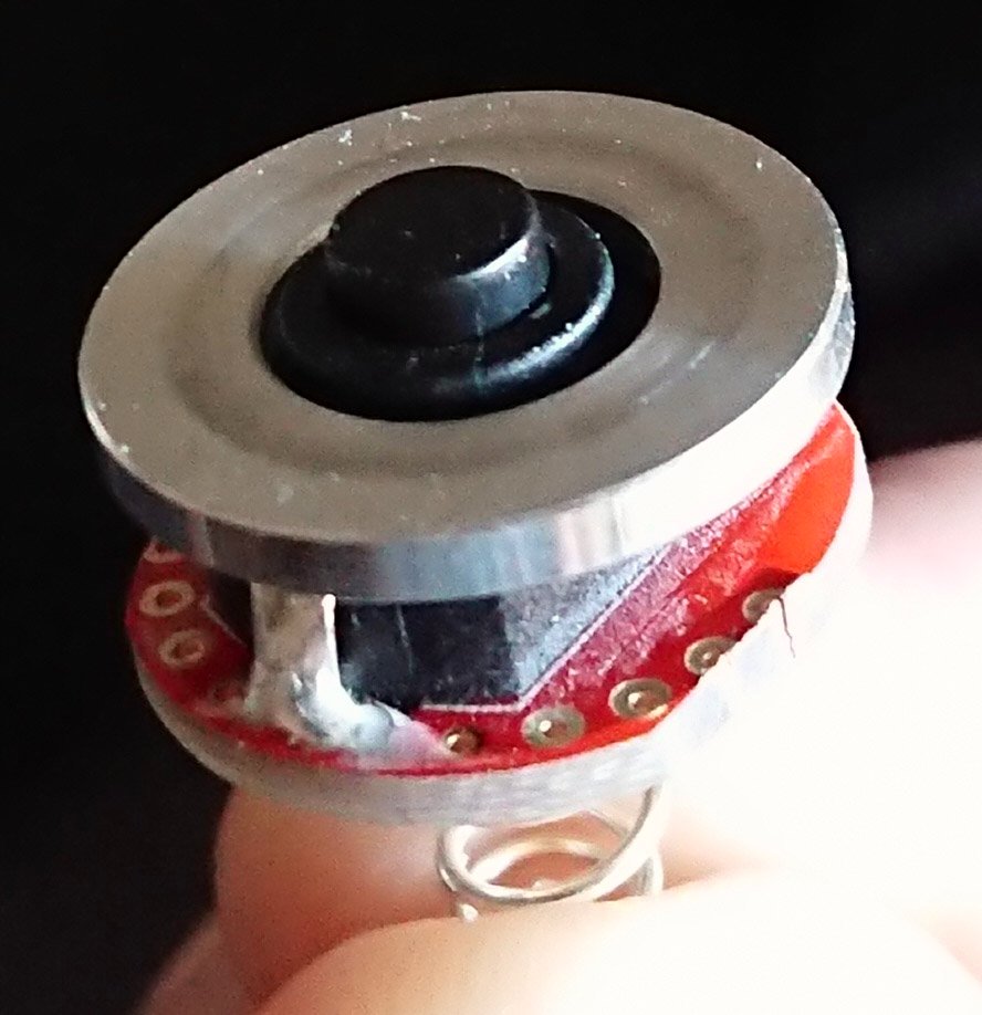
Looking at the diagram, the booster chip bypasses the LED (the led being a diode itself will not allow reverse current). So a diode may be needed either after VIN or before the ground connection to the chip. Looking at the top side of your board, it appears there may be enough room to cut either the positive or negative trace and insert a diode. Questions is, what diode would be a good candidate. Also, will the voltage consumption via said diode be enough to make the circuit not work when a cell drains to a certain voltage. That might actually be good as a low voltage indicator.
I would be very happy to do some surgery and try when my boards arrive, but I would need some guidance on what diode to try.
Sounds logical enough! I should be able to scavenge a diode from a “for parts” driver and cut that into the Vin connection. It may not be a perfect match, but I would think good enough for testing. Hopefully I’ll have some time to try that tonight.
looks like you are using Eagle for design, if not Diptrace i cant help you giving a basic design with the diodes arranged
17/20mm board with LVP based on loneoceans design but with more stuff going on
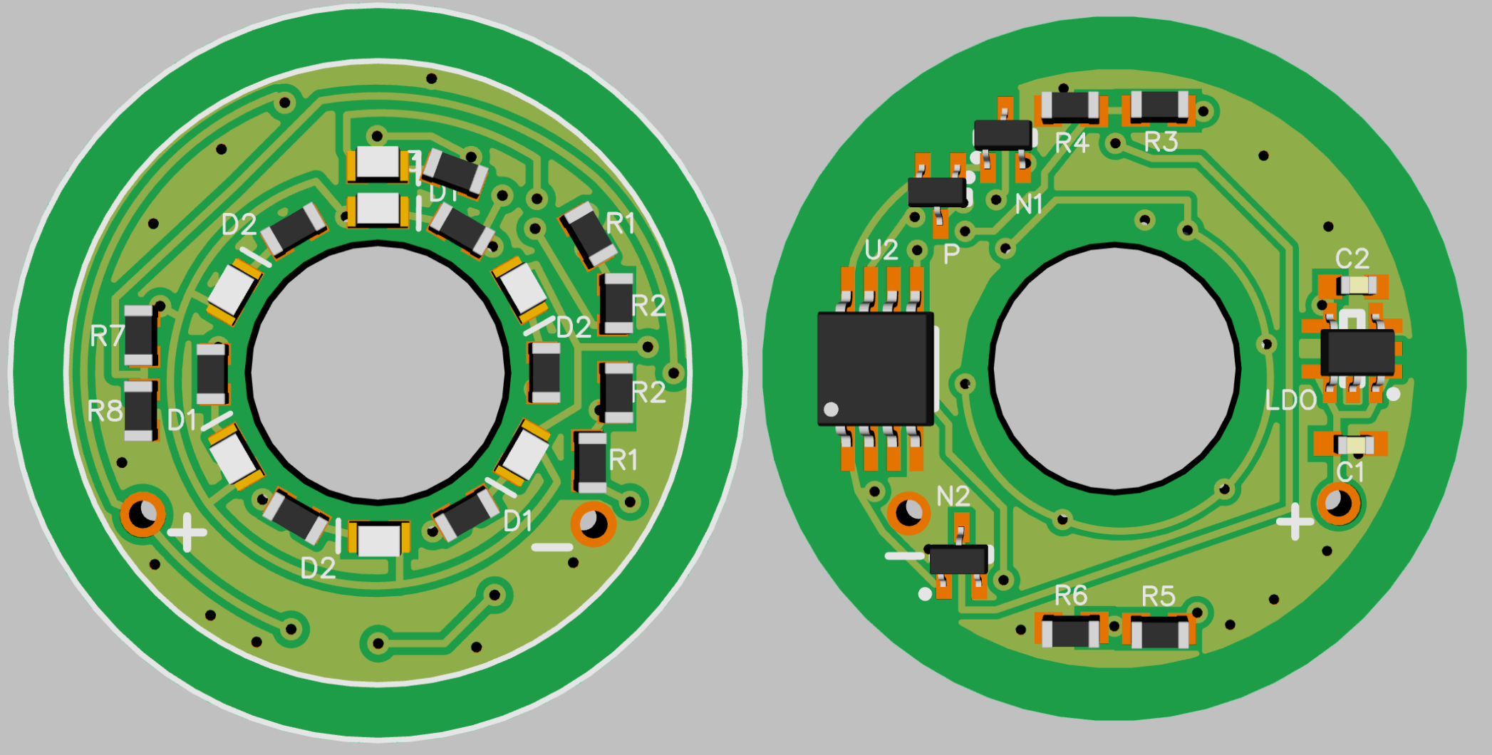
0603 LED and 0603 resistor barely fits the central ring with custom pads for reflow only
for people who are afrid of dual layer reflows that red glue that gets hard above 85°C helps a lot, but its no problem to put the LED board on a post or clamp and apply 2. side solder paste with a tip and parts stick to the paste on both sides usualy fine if not too heavy