My impression was that the low current setting only turned on a led and did not do anything else (like terminating charge).
Good. I see no reason to actually terminate, and this means the cells can get full-filled. :THUMBS-UP:
If this is so, my guess is high current diodes in series would be needed to set modules in parallel without magical smoke issues. However, I wonder how much current crossflow could appear fine tuning Vout within ≈1mV.
Thanks for the input.

If using a new Soshine 18650 LiFePO4 cell should I leave the 10% precharge connection unchanged or should I de-solder it?
DoubleA, leave the precharge connection unchanged, it is meant for gentle charging of over-discharged cells. Reason to disable it is if using these TP5000 modules as led drivers (HKJ mentioned this here).
Cheers 
Yes I understood that part, it’s about recovering over-discharged cells, but I was talking about new cells, probably with some protection circuitry built in. Should I still leave the connection unchanged? ![]()
Let's make it easy, DoubleA:
¿Do you plan on using this module as battery charger? Leave the precharging setting as it is.
¿Do you plan on using it as a led driver? Remove it. If not, you won't get the full driving current for low Vf leds (below minimum cell voltage thresholds).
Cheers :-)
P.S.: as a gross barbarian I am, I'd probably remove the jumper anyway. :-D
Ok I got that… Thanks, I’ll leave the connection as it is for now.
Now just have to decide which one of these TP5000 modules to buy since aliexpress shows a handful of different variants.
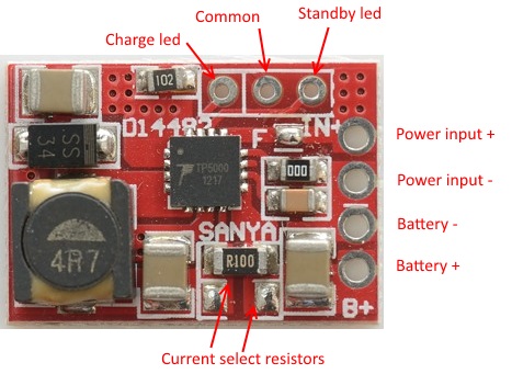
About that current select resistor part, should I add a new resistor in the empty slot or should I just replace the existing resistor to a different value? I wanted to charge 14500 cells at 300mA current so please help me out here.
The two resistors are in parallel, adding a resistor will increase the current, you want less current. That means you have to remove the existing resistor.
Ok, so the existing SMD resistor R100 (0.1Ω) will give 1A charge current, and if replaced with a 1Ω resistor then the charge current decreases to 100mA right. But this is where it’s confusing to me, according to your table why does 0.2Ω give 500mA Current? shouldn’t that be 0.5Ω?
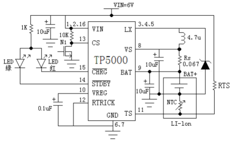
The data sheet for TP5000 says the formula is: Rs=0.1V/Ibat (Rs in ohm, Ibat in Amps)
Thanks for the formula. Guess I will remove the existing resistor and add three 1Ω resistors in parallel to get 0.33Ω so with that formula this resistance should give 300mA of charge current. :+1:
Do not expect the formula to be exact, there is some component tolerances.
I’ll check the current output with my multimeter before I implement it. ![]()
I finished my setup and the LiFePO4 battery is charging fine but there seems to be one problem, the LED does not work?? What could be the problem, I tested the led before I soldered it in and it was fine then. Could it be the very low current draw probably not enough juice to power up the LED? or did I mess things up? My LED pins went like RED to Standby and Green to Charge. Or does the LED indication work only with ICR/IMR mode?
Current draw at input when checked with a USB doctor is 5.03V and 0.1A.
Did you use the supplied led or you own? If you used your own it could be the wrong polarity (That could also be the case with a supplied led, but that is less likely).
I used the supplied led. It was a common cathode led. Does this module use common anode?
btw, I finished charging the cells, they were not warm at all.Used Soshine 14500 LiFePO cells.
I believe that the TP5000 requires a common anode or two separate leds.
Well that explains. Let me try CA leds and I will let you know the results.
Tried Common Anode and they work fine. Why on earth do sellers ship them with the wrong type of LED?