Thank you! Great to know!
This means mine will go in this light from kiriba-ru which uses the body tube of the C8:

Thank you! Great to know!
This means mine will go in this light from kiriba-ru which uses the body tube of the C8:
Cool, let me know how that works for you,
Has anyone else used this FET switch, they seem not to last more than 2 weeks before they stop working… for some reason the coin cell just craps out. ill Raise R1 value to 4-5kohms to slow down the charging current and see what happens.
The charging current should be fine. But maybe the discharge current stresses the cell too much. The maximum continuous discharge current is 0.1mA.
Try increasing R2, by a lot.
I thought about that as well… but the weird thing is that they just die on there own, the light would be sitting unused for a week with a fully charged 18650 in it, than the next thing I know when I try using it is its dead, the coin cell voltage is at 0. anyway I have some more boards on order, ill increase R2 like you said and see how that effects the battery and the FET gate.
I got a major problem here on my builds I can not firgure out
I removed hysteresis and adjustable reference, but it is still odd
If I put the board on my PSU and it is on I can connect it it is lightning up, reducing the voltage makes it go red and then turn off
But when I increase the voltage it does not turn on anymore or go from red to the other color
I measured the voltage on the ina+ and b+ and it is higher than the reference, but I got to disconnect the PSU to turn it on again
PS
finally found it running the comparator on 2.8V LDO with a higher voltage from your voltage dividers at levels above the 2.8V did not work
running the Maxim 9022 with 2.8V reference from LDO and Vcc on battery supply works now
seems it can not compare higher voltages than its Vcc or close to it
So final results for the Tail and Aux boards are found
2S atm untested
Vbatt x R4 / R3 + R4 =Vref
When battery level drops below 3.30V, Light up Red.
3.255V x 360K/270K+360K = 1.86V
Calculate divider for LDO reference R8 360k fixed for one and 2S
1.86V=2.8V*R8/(R7+R8)
R7=0,531*2.8*R8-R8
R7=182k
on 1S is max 4.35V, the calculated reference voltage should stay below 2.5V for 2.8V LDO
4.2V x 360K/270K+360K = 2.485V
2S
is max 8.7V, the calculated reference voltage should stay below 2.5V for 2.8V LDO
8.7V x 390K/1M+390K = 2.44V
6,63V x 390K/1M+390K = 1.86V
Vbatt x R6 / R5 + R6 =Vref
When battery level drops below ~3.00V, Turn off all LEDs.
for 1S
3V x 360K/220K+360K = 1.86V
for 2S
5.88V x 390K/845K+390K = 1.86V
calculate like above just with another battery voltage 2.8-3V
The tail boards run with an 1kOhm resistor as bleeder this works with relative low current drawn from LEDs
Note the more current the LEDs draw the more voltage drops on the bleeder so battery voltage is higher than the calculated values
With standard hysteresis there is a fade between both LED groups and LVP shut down
this is PWM because when the comparator switches the LED off, then the voltage drop on the bleeder is gone,
so it switches on again just to notice that with the voltage drop again it is too low, aso
with battery voltage dropping the PWM cycle gets shorter and fades out

without a resistor like with new Aux boards it has a devent hysteresis

Nice work lexel!
1. If I put the board on my PSU and it is on I can connect it it is lightning up, reducing the voltage makes it go red and then turn off
But when I increase the voltage it does not turn on anymore or go from red to the other color.
I had the same problem & it turned out to be because of the high bleeder value I was using.
2. finally found it running the comparator on 2.8V LDO with a higher voltage from your voltage dividers at levels above the 2.8V did not work
running the Maxim 9022 with 2.8V reference from LDO and Vcc on battery supply works now
seems it can not compare higher voltages than its Vcc or close to it
The 9052 has a set Vref of 2.5V also a VCC of less than 2.5v will put the compactor to sleep, the 9039/9039 is set to 1.23V and the 9040/9043 is set to 2.048, which one are you using?
3. Vbatt x R4 / R3 + R4 =Vref
When battery level drops below 3.30V, Light up Red.
3.255V x 360K/270K+360K = 1.86V
I’m surprised you having it trigger at 1.86V, this is where I lost you.
4. 1.86V=2.8V*R8/(R7+R8)
R7=0,531*2.8*R8-R8
R7=182k
on 1S is max 4.35V, the calculated reference voltage should stay below 2.5V for 2.8V LDO
4.2V x 360K/270K+360K = 2.485V
Now I’m getting back on track again.
Whatever magic you did, I hope you’ll be releasing them for sale soon!!
Lexel are yours also a FET switch? Does that allow the main current to bypass the switch?
The magic is use a Maxim 9022 which has no internal reference and only needs 2.8uA
The reference voltage is generated by a voltage divider off the LDO,
this is not so good when the LDO drops out of regulation at about 2.9V
(if you want the red burning quite down to a very low level as the reference voltage drops also, not sure what would happen)
positive is that the 9022 costs only 33% compared to the 9052
on the 9052 with a diode on vcc it could shut down at a higher voltage not draining the battery to the edge
with the 9052 you would need a 5V LDO for 2S lights, I am pretty much set at 2.8V for my lighted boards
you would run otherwise in the same probems like I had with higher compare voltages than the Vcc of the Maxim, as you cant run it on 8.4V
this would on the other hand give an option to run LEDs with less than 2.2V like green, red, orange and yellow as pair in series to cut current to half
especially on yellow and orange they get power hungry if you want them not dim
This is only lighted board I do not have a FET switch as local switch as the battery question is not solved,
yes basically having sort of button lithium rechargeable should work with a small coin cell if a diode is used to charge it
I asked the topic creator which battery and holder he is using but got no reply
There is no holder.
The battery is in the parts list in the first post:
Seiko MS412FE-FL26E
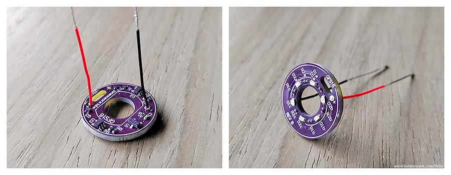
Correct, the battery tabs just get soldered to pcb pads.
I tried everything with the FET switches including Lexel recommendation, the battery just dies in under 2 weeks.
a solution would be the rechargeable version and a diode on the board, so the coin cell gets charged by the main battery if the voltage gets lower
https://www.mouser.de/ProductDetail/Seiko-Instruments-Micro-Energy/MS412FE-FL26E
Mouser and others dont ship those batteries outside USA
You can get them on Ebay from China as I did.
Fady, you're right, you can change the resistor values to change the threshold voltages. Fady, are you also still having problems with the battery? It's fairly different to solder such a small package and you need to be very careful since too much heat can damage the cell. I've been using my lighted FET tailswitch in my main light for the past half year bringing it on many outdoor camping trips and it's been still working great.
Lexel, yes the MAX9052 is definitely suboptimal in quiescent current consumption of ~55uA typical. LEDs should draw on the order of ~200uA for 3 LEDs, so the comparator definitely is a large power hog. For your voltage regulator, you can use a better one I think, since there exists a lot of sub 1uA LDOs, and yes you can then use a much more jellybean comparator.
Thanks everyone for the support! When I have time I'll maybe do a quick update on the design.
welcome back loneoceans!!, I still have plenty of parts… ill attempt to build again and be careful when soldering the cell, on the other hand Lexel came up with an improved design based on your LED board, he added a LDO regulator to have a constant voltage drop across the bleeder thru the entire battery voltage range… so led current is constant therefore voltage sensing can be easily calculated. check it out here.
Sounds good, well the main idea was to keep this board as simple as possible! I think the LDO is more for a constant LED brightness. The voltage sense inaccuracy isn't so much of a big deal if the bypass resistor is small <=1kR, and the voltage divider is large (and everything else is within spec).

Anyway it's true that the quiescent current for my Rev A one is a little large (>50uA), which is a large % of the LED current draw (~200uA for 3 LEDs but depends on brightness), so over lunch I did a little revision replacing the comparator with an ultra low I_q one, and added another ultra low I_q voltage reference. I don't mind the LED brightness changing, I suppose it's easy to add another v-reg, but I'd prefer the LED brightness giving me another estimate on battery voltage, instead of just losing this information in the Vreg as heat. LED side remains the same..
Total I_q is an order of magnitude less and now closer to 5uA + LED draw. More details soon when I have time!
Cool!! Hope you release this on ashpark soon, correct, the LDO is for constant led brightness but it also allowed the use of a larger value bleeder without effecting the accuracy of the voltage reading since the compactor Vref was driven off the LDO divider circuit which also remained constant… on your Rev A board… increasing the bleeder value to 1K increased the hysteriss by a lot and really messed up the accuracy but I’m glad you updating this design!!!
Awesome, I can’t wait to see what you’ve come up with! Please include a BOM when you write about it (I’m mostly curious about what v ref you’re using and how it’s wired)
More to come soon and I'll update the front page, but here's a link to the OSHpark PCB design.
https://oshpark.com/shared_projects/L27QGJFW
*note: this Rev B board has now been successfully tested and recommend for your own builds*
I rotated the PCB 45 deg because OSHpark tends to make snap-off cutouts on the 4 sides which can cause the part with the cut-out for the tiny battery to break. Hopefully this helps.
Total I_quiescent:
Total: ~5.5uA
Previous I_quiescent = ~70uA, so this should be a >12x improvement in standby time after the LEDs turn off, and a good 30% or more in regular standby time with LEDs on.
Components:
Features:
More to come soon!
I had some time to put together the Rev B of the GFS16 LED Taillight board.
Here's how it looks like. The OSHpark boards turned out great, especially with the 45deg. rotation to avoid a chance of the oval-cutout breaking.
The board seems to work just as expected, and has an actual measured current draw of (5.6+-0.1)uA at a 3V LED Turn-off threshold, exactly as expected. This is over 10x LESS current draw than my Rev A version, so I think that's not a bad thing :). As the battery voltage drops, current draw should drop further.
Made a quick video of the board in action, and here's it with a 330 ohm series resistor and a power supply. The threshold voltages are about 3.4V and 3.0V for Low and Off respectively. Note that the bigger the bypass resistor, there will be a larger possible error of the threshold voltages from the voltage divider, as well as a larger hysteresis. This was discussed in some detail in previous posts.
I've also tested this with a 560R bleeder resistor across a Convoy S2+ standard driver, with R3 = 681kR. This gives a 3.55V low-voltage threshold (hysteresis at 3.75V).
Regardless, I just wanted this board to be simple and no frills. Tested all the way down to 0V and it fixes an issue with the previous Rev A design (where if the voltage drops below ~2.5V+, we were out of spec for the comparator, so the red LED could come on again dimly). No such issues for Rev B.

OSH Park boards and parts list are available in the previous post as well as the first post.
Many thanks to all the support I've received on this forums, members who've had good success building their own despite the annoyingly small components, and feedback and suggestions for improvements! Again I understand it's not the perfect tail-light, but it does provide some simple extra features over a regular tailight board.
[Edit] - I understand the components are a little bit of a pain to solder by hand... when I have time I think I'll have a go at changing the components to be larger and easier to solder.
Enjoy!