Thanks for the contributions. There are some older posts on using a sound card input, then using some type of scope software to access the waveform. Anyone want to try this, with details?
My suspicion is that different solar cells will have different biasing characteristics/response times. If we can get the details on a specific solar cell, then the results can be duplicated.
I am very interested in measuring PWM, too. But not just flash lights but also regular lights and especially display PWM. Displays are not as bright as flash lights, especially on lower brightness levels.
Your thread greatly helped me in “building” my own biased BPW34 circuit, thank you for that! I just replaced your 8K resistor with a 100K resistor. I needed 100K because lower resistances would not display much detail on my oscilloscope due to low voltage. Now my voltage range is in between 20 mV (lowest display brightness) and 400 mV (full display brightness), which is great.
I just wonder if the 100K resistor as opposed to 8K makes the photodiode less responsive or introduces additional noise. Do you know about that?
You mentioned the Thorlabs DET36A2. Do you know if it has a similar output voltage when connected to an oscilloscope?
I am tempted to buy a Thorlabs detector in the hopes of getting less noise and more precise measurements. Maybe those devices are the ultimate PWM measurement tools. However, I do not know how much voltage they deliver. Maybe the biased ones would do, or maybe the more expensive amplified photo detectors are needed. Any ideas?
@maukka You were mentioned to own a device simliar to the DET36A2. What device are you using, and do the voltages differ to the do-it-yourself methods in this thread?
And finally, you asked for other devices that can measure PWM. There is the portable Fauser LiFli (Fauser Elektrotechnik - Light flicker meter LiFli - Description), which can detect flicker up to 400 kHz. A downside is it will not directly tell you the frequency. You can listen to the audio output to “hear” frequencies. Ultrasound is converted into audible sound. If there is flicker, the device tells you a rounded percentage on an LED scale. It even has an oscilloscope output. Sadly, the output of my device has a lot of noise, making it less useful for low brightness measurements. I believe it is usable for higher brightness as seen in flash lights or room lighting. The device itself will not tell you a percentage if the light is below 100 lux.
I admire your skills Terry and thank you for all the testing. :+1:
One question. You stored the sensors in anti static bags. Where were the lab Snacks stored? ![]()
I just tried a 100K resistor with the OSRAM. The noise, amplitude and sensitivity didn't seem to change, but the fall time increased about 4X, causing clipping to occur sooner. However, whatever seems to work - which is why I said "the resistor values on my schematics can be taken with a grain-of-salt. My values are just a starting value. You may find lower/higher values work better in your circuit". . Was your supply voltage the same as mine?
The Thorlabs DET36A2 uses a 12V battery for biasing voltage (significantly higher than what I used), and they recommend a 50Ω BNC cable impedance matched to a 50Ω terminator. Can't say if this would give better results for measuring display PWM. If you decide to buy one, let us know the results.
There should be a good joke here, still trying to think of one . . .
Someone’s belly? ![]()
I use a 9 V battery. Actually I do not know which manufacturer my BPW34 is from. I have read the Vishay manual which states a 10 V bias and 1K resistor give the diode 100 ns rise/fall time: https://www.vishay.com/docs/81521/bpw34.pdf. The OSRAM PDF differs and mentions 5 V, 50 Ohm, and 20 ns: https://www.osram.com/media/resource/hires/osram-dam-2495812/BPW%2034.pdf
It seems it is not a simple task to make the most out of one’s circuit.
This is a good thread. ![]() I managed to miss it when it was new, but I wonder if you might be able to scope the results when using a regular LED as the sensor?
I managed to miss it when it was new, but I wonder if you might be able to scope the results when using a regular LED as the sensor?
I realize this idea was ruled out since they aren’t optimized for use as a photodiode and may produce less than satisfactory results. But I wonder what the results actually are. I’ve been able to measure frequency pretty effectively with a plain XM-L2 inside a Convoy S2+ head to focus incoming light onto the LED… but I don’t have a way to see the actual waveform.
Problem is - I don't do modding, so don't have much in the way of LEDs to test. The only LED's I used during my sensor test, was a stock off-the-shelf LED like this one. I do remember trying to use the white LED as a sensor, and it hardly worked at all. HOWEVER, other LEDs (actually used in flashlights) might work better. If you or anyone else want to mail me a particular LED, I will certainly volunteer to test it (will return if they are expensive).
Right. I shouldn’t assume everyone has extra Cree LEDs laying around. ![]()
Hey, if it will help further BLF driver development, I’ll send you some emitters for free. I’ve got lots of different LEDs that are just lying around right now because I pretty much lost all my modding time to a change in work hours a while back.
I’ve got…
- a couple hundred cheap XP-sized “1W” Chinese emitters. These are “bare” in a pick-and-place roll.
- several XP-E2 on 20mm non-DTP Aluminum MCPCB’s
- a few XP-L HI. I can’t remember how many, but not much. I’m not using them, so they are available.
- a few XP-G3. I don’t know how many of these either. I haven’t counted recently.
- one Sofirn Q8 MCPCB still populated with the stock XP-L HI emitters. I replaced the whole thing.
- a couple of de-domed Luminus SST-90 on the stock DTP MCPCB’s
- some other random XM and XP emitters pulled from lights that I’ve modded.
- maybe still a MT-G2 around somewhere as well
ToyKeeper, the offer is open to you as well, of course!
EDIT: To clarify, I’m not offering to send “all of the above” for free. I’m just listing what I have to let you know that I could send you several kinds. But if you decide you do want it all, I can let it go for a small amount. ![]()
Thanks for the offer,
I wouldn't have time to test all of them - but if you could pick about four of them - that you think might work in reverse to measure PWM - I will test them - to see if they are anywhere near as good as PIN photodiodes. Would be an interesting experiment. PM me.
PM Sent.
ToyKeeper, do you have any input about what kind of LED is the most likely to give the best results as a photodiode? Is it the same property that makes a good LED or something else?
Mostly, the same things which make it good at producing light. But in particular, a large die surface and probably a relatively high Vf. That raises the amount of voltage it’ll produce. A reflector helps too. And being a recent LED helps, instead of an older model with a slow response time. Upgrading from XM-L to XM-L2 allowed me to measure a bit better.
If an emitter normally starts lighting up at ~2.4V, it’ll generally produce up to 2.4V when a light is shined at it. But if it’s a higher-voltage model which doesn’t light up until ~4.8V, it can produce twice as much voltage, which might be easier for the attached DMM or scope to read. Generally the range is from 0 to the lowest voltage which will make it light up.
I have a bunch of broken lights I could take apart for parts if it would help. For sensor purposes, it just needs the head of the light with two wires sticking out. I have several dev hosts set up this way so I can access the driver for easy flashing and testing purposes… I generally just grab one of those and clip on some DMM leads.
I’m not sure if it helps to remove the phosphor layer. I haven’t tried. Also not sure if it helps to add something to pull down the signal faster after each pulse. It probably does. With just the emitter though, I can at least confirm it handles 36 kHz PWM with no problems.
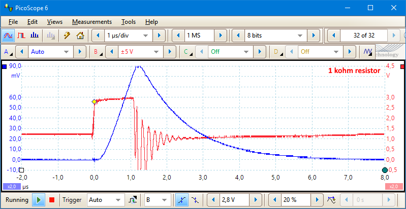
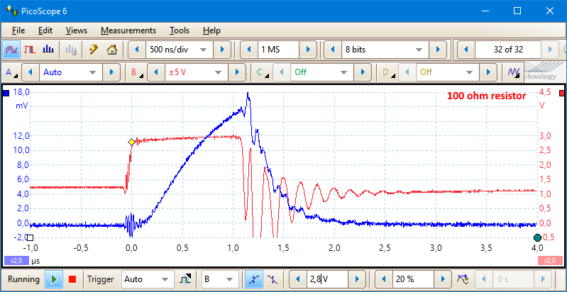
When I tested flashlights I used a photo diode parallel to a resistor directly connected to the scope for measure PWM. The value of the resistor has a significant influence on the fall time, but also on output voltage.
The red line is voltage on led, the blue voltage from photo diode.
HKJ, can you sketch out that schematic? I wouldn't have thought that a resistor in parallel with the sensor would work, as the reverse bias would cause the current to seek the path of least resistance, mostly going through the resistor and not the sensor.
I do not use any external voltage, only the voltage generated by the diode:
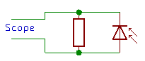
I wanted a simple circuit without any battery.
Interesting. For future reference, what photo diode did you use (manufacturer).
Thanks ToyKeeper, that makes sense, from my original post: [quote] It was also noted that the best sensors in this review had large sensor areas. [/quote]