Pretty cool! What driver is this?
That looks downright scary Sk. Nice work. ![]()
That’d be mine. If you happened to know that and you’re asking for specifics it’s my v3.0 constant current 4Ch driver in 17mm.
Omg, with the current FW offerings this old board is my new favorite 7135 driver!
Can be populated from a 105c and a otc.
Dual channel 1x / 7x 7135.
Runs popular FW including star moonlight special and (wait for it) BLF-A6 without mods.
Fits in Convoy S2+ pills, with non filed retaining ring!


Awesome!
Yes, sitting on top of the ring is not ideal, and even with a tinfoil hat around it, and set inside I gained 400lm. It was mostly and experiment. I used some heavy solid core copper wire we use on our machines that I found laying around in the shop, and hand pounded and bent many pieces to connect the mcpcb to the Lexel T/A Infineon FETDD TN42 driver, to see if/what I would get. Well the pipe fitters have a term/word for it “Bones” many bones were made till I got the right length and bends in the leads to be able to solder the leads to the board or driver with out breaking the solder joints or ripping the contacts off either, and bolt the TN42 style driver up to the light. This heavy solid core wire is not manageable to say the least. I wasted a good brand new massive SD75 XHP70 board in the process. I just wished I would of done this in a light that had better sinking and fins on it. The TN42 is not the best choice, as in seconds this thing gets amazingly hot, the GT or SD75 would have been a better host, really stupid in the end on my choice with all the effort but it was a rainy weekend?. ![]()
The carrier springs had 18awg Normal wire (silicone) bypass’s and the center positive contact was soldered directly to the carrier mcpcb, brass screws connecting the stanchions to the boards, with 4xVTC5D’s 2S2P it’s a potent power plant.
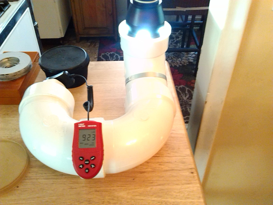
I am building an integrated sphere and have a problem.
My Luxmeter has a maximum value of 200 kLux, but my Imalent DX80 emitts more light.
Does anyone know how to mod a luxmeter, that it shows lower values. Can I add a resistor? How does it work? Has the sensor AC or DC Current?
Its a UNI-T UT383 BT.
Diffuse the light. That will take some balancing to get it right but it will be easier and more reliable than tinkering with your meter.
Thank you, that was my second idea, but my favorite was to change something in my meter.
Now I added a DN25 electric installation tube with 6cm length, to put the sensor to the outside of the sphere. It lowers the readings by factor 10.
No 30.000 Lumen eqals around 50.000 Lux. This means my sphere can read around 100-120 kLumen. That may rest around 2 years to get such a flashlight, I think.
Measure a lower mode in the sphere and calculate the relative difference between that and higher modes in some other way (ceiling bounce for example). Or put a diffuser/neutral density filter in front of the lux meter. Or what you just did ![]()
I have alread a Lumen-Box, but I noticed that the readings for over 10-15 k Lumen are too low. So Now I make further readings in the Toilette. But I wanted to get better readings for all output levels of a flashlight. For my Imalent DX80 and others like Olight X9R, Acebeam X80 and upcoming flashlights. Thats why I build the new integrated sphere.
And with diffusing the light before it hits the luxmeter, I will get good readings, I hope.
If you want a very neat way to diffuse the light you can use a satellite sphere (which is indeed called a diffuser in the literature) where the luxmeter sensor used to be, and put the sensor in there (you even gain some integration). The sensitivity decrease can be set by the size of the connection hole: the inner surface area of the satellite sphere divided by the surface area of the connection hole gives you the decrease of the sensitivity.
(I made one sphere with diffusing satellite sphere: Integrating sphere #3 (portable and overly stuffed with features))
Last night I built up this old SK68 driver board from warhawk-AVG and then stacked it on the stripped driver board from a SolarStorm SC02 then flashed it with single mode (100% + hidden strobe) eswitch-13 FW from Tom_E then installed a Chinese no-name-brand XP size 365nm UV emitter that, other than a high vF performs very well and actually outputs a good amount of 365mn light (25mm ZWB2 filters on order from AE, does have a bit of visible light too).
This is one of the lights for my next GAW.


Power and GND connections between boards so only LED wires and the one switch wire are on top.

Looks good. How is the output relative to a FET triple?
I didn’t have a chance to compare, but the light is quite bright. I spec’ed the driver to 4.2a output and 10.5a input, and ran the light on a Sony VTC6. I think that puts the light at around 2000 lumens, so I don’t think it puts out as much lumens as you can from a high output FET triple if you’re only concerned about the lumens. However, there’s nice things you get from so many lumens from a single led. I will say that the light gets hot pretty fast. One word of warning, just make sure you work out the length of your battery in relation to your switch spring and battery tube since the driver comes with a brass button for contact. I crushed one of my batteries a little while testing.
Crushed because it was a longer button top or crushed because you had a long/stiff bypassed tail spring?
Crushed because there is a solid button which can’t deform under load.
That either meant having a longer cell like contactcr said, or perhaps he dropped the light, and that can easily result in a damaged positive electrode.
Finally upgraded the old beaten up TK35 clone with a Luxeon V (4000K) running at 6A and a LM3409 buck driver with Anduril. Should be around 2000lm on turbo with a comfortable 2.6A battery draw.
Very nice beam with the smooth stock reflector. Good tint.


Not exactly a looker, I know. Neither on the inside nor on the outside. :laughing: And you haven’t even seen the ugly bits.
Works like a charm though. Better than new.

what did you use for your centering ring?
A piece of acrylic, turned on the lathe. It’s mostly for visual guidance during centering though, I only had a 16mm star where a 20mm would be the right size, so that was a bit tedious.
It doesn’t have to bear any load since the LED pill rests against the reflector flange.
It also helps keeping any dirt from getting inside.