BLF driver programming key v3.2 launched on Oshpark

I found aligning it on 0.8mm pads with only one via would be hard, but yes generally you could say make at least 2 of the pads as viases so the key aligns to the other pads
I think some people are underestimating how small this thing is with only 1.3mm pitch

likely best would wotk get 2 of the outer connections as viases, which ones they are is less important, but I designed 2 pogo pins to be sticking out further on the key (- and 2. centering via)
the further their disteance is the less gets twisting an issue just notice if used only 6 connection pins the max distance is 2.6mm

also thinking about a key with a header for USBasp

Subscribed!

WOW!

:+1: :arrow_right:

It still looks clunky to me.

I say again, no need for extra alignment pins, just the six required for functionality. Make two of the pads (preferably spaced as far apart as possible) also vias, and it will self-align under pressure, all pins the same length.

Your key is far too wide at the bottom, no reason for this.

Yes it should have a header to accept the standard USBasp.

Take a look at e.g. https://www.tindie.com/products/madworm/tiny-avr-isp-pogo-pin-programming-adapter/

and

to see how a half size (1.27mm spacing) 1/4 the area thing looks. And buy one for $6.50

By the way, this is very very small, not something for the inexperienced to meddle with, or try to assemble without good skills.

As I’ve said before, this seems to be re-inventing the wheel, it’s all been done before, but maybe there is a better wheel to be made ?

Frankly for our purposes only four pins are needed, Vcc and Gnd can be supplied otherwise, e.g. with croc. clips.

clunky?
if we use the standard idiot proof USBASP header with 10 pin and the plastic casing there is no means how small the front of the adapter is
really noone wants to make a 10 to 6 adapter cable just to make the programming key 8mm thinner
lower end is 12mm and upper end 22mm right now, this is a lot smaller than my house door security key, no need to make it smaller than this

to give you an idea how small we already are look at the v1.1 size compared to my house key

as you self said the micro Key you can buy is too small for really safe flashing if you dont want to check if it sits right with maginification glass
there is really no need to make it smaller than an average Attiny MCU is just because it is possible with 0.33mm pogo pins heads on 0.5mm tube going to 0.7mm pin distance

we are not going to challenge how small it can be done, who cares if the pin distance is 1.27 or 1,3mm in real life on just 2x3 pin you wont see any difference with pogo pins anyways,
if you really want to buy the “standard 1.27mm” key you can fit it on my programming port with no problems

the additional Pogo pins are totally optional making placement and aligning of the key easier for people who can not solder 0402 or 0603 anymore because of age (Eyes or hands not allowing it anymore)

but you got to have some error margin in placing it on a driver
you ever destroyed a MCU because the SOIC clip or in this case a pogo pin key went off during flashing? No I dont want it as small as possible exactly to avoid this

and on complicated driver designs you are really happy if you can route a trace between things

so if you want to pay 10$ with shipping for a 1$ parts and 2$ labor costs adapter go for it noone is going to stop you bringing your drivers with this port on market

any chance you have a 0.8mm through hole model for Eagle? I would like to add this programming feature to the BLF ultimate lantern. The smallest through hole available is 1.6mm. Guessing the through holes are 0.4mm? I might be able to figure out how to mod the existing symbol but my CAD skills are weak at best.

Well if you find the key to wide you can always grind it down.
Or you buy at tindy. 50mil ist 1.27mm vs. Lexcels 1.3mm pin pitch.
Difference is 0.06mm with a row of 3 pins.

@lexcel
I would flip the silcscreen upside down on the right side in the picture.
To read the pin names when you use the key.

Also on the driver, you cant read the pins when the text is between the two pad rows

For the “manual” for the key I would advise people to clean the driver with isopropanol.
Maybe use a good contact spray?

I like the idea, but which drivers can we flash with it?

Lexel has said that as he moves forward with new driver designs, they will be made to work with this programming key. Also, anyone who wants to may create compatible drivers.

Mostly, I just want this to be a thing… like, yesterday. And I hope we can get someone to manufacture keys and sell a flashing kit. It looks like a huge upgrade to how we’ve been doing things, and it could enable the use of smaller and fancier MCUs.

Lexel, this is huge and awesome. Great work!!

Please don’t make it fiddly, having to play with croc clips and stuff. Make it fit one way and easy to connect.

Lexel, I must apologise. Somehow I had got the wrong impression that you were duplicating the 0.1 inch pitch connection that has been around for ages.

I now realise that you have chosen the 0.05” (1.27mm) pitch micro key, which is the correct decision.

The “standard” pad layout is the same, just 1/4 the area.

The tindie micro key (others may be available) shows a reasonable looking pad layout, with a square pad to indicate correct alignment. I’m not sure how more “foolproof” it needs to be.

See https://www.tindie.com/products/madworm/tiny-avr-isp-pogo-pin-programming-adapter/ and look through the photos.

My suggestion would be to include the USBasp circuit on the key, make it an integrated solution, micro USB connector.

See e.g. USBasp - USB programmer for Atmel AVR controllers - fischl.de for some ideas. Perhaps there are more recent developments ? I just have the FastTech USBasps which seem to still do the job, but connecting them up is a pain. An integrated pogopin key that you just have to press against the back of the driver would be marvellous.

PS: If it could also do fuse restore using HVSP that would be icing on the cake.

That would typically fry the rest of the driver. HVSP usually involves unsoldering the chip first.

I just found this thread, and I really like the idea.
I have one suggestion, redo the layout so it is skinny, especially the tip with the pins. That way it’s as maneuverable as possible. It should feel like a probe when handled, not like a car key That fat handle was designed for twisting an ignition switch.

Yes but no. The pogopin adapter connects to the necessary pins I think. But they may, or may not need to be isolated from the rest of the driver during HVSP. The obvious one being the reset pin that gets 12V up it.

As for the other pins, it depends what’s attached to them, and whether they might give some interesting flashy effects during the process, or stuff the attached circuity if normally configured as an input. If so, maybe a series resistor would prevent that. That’s also if the LED was still connected.

To disconnect at least the reset pin would be traditionally done with a zero-ohm resistor. But can also be done at zero cost with a suitably designed track-cut area on the driver. Skills and a scalpel required. Then the track cut reversed with a solder splash over the top.

Or be radical, and add a seventh pin and maybe a small diode or FET to do this automatically.

Or reverse this idea, make the connect/disconnect points part of the layout, solder bridges connect them by default, remove it with skills, a sucker or braid if you need to reset the fuses.

Anyway it’s just another bonkers idea that would cost nothing to implement on drivers, if area permits. And for anyone into bespoke firmware (the whole point of this) it takes away the risk of bricking a driver. With all the nausea that would follow if already built up into a torch. Or simply the cost of the driver and sheer inconvenience of bricking one.

A quick google: https://www.instructables.com/id/AVR-HVSP-Fuse-Resetter/

Interesting that a tiny remote control 12V cell is enough to do the re-set.

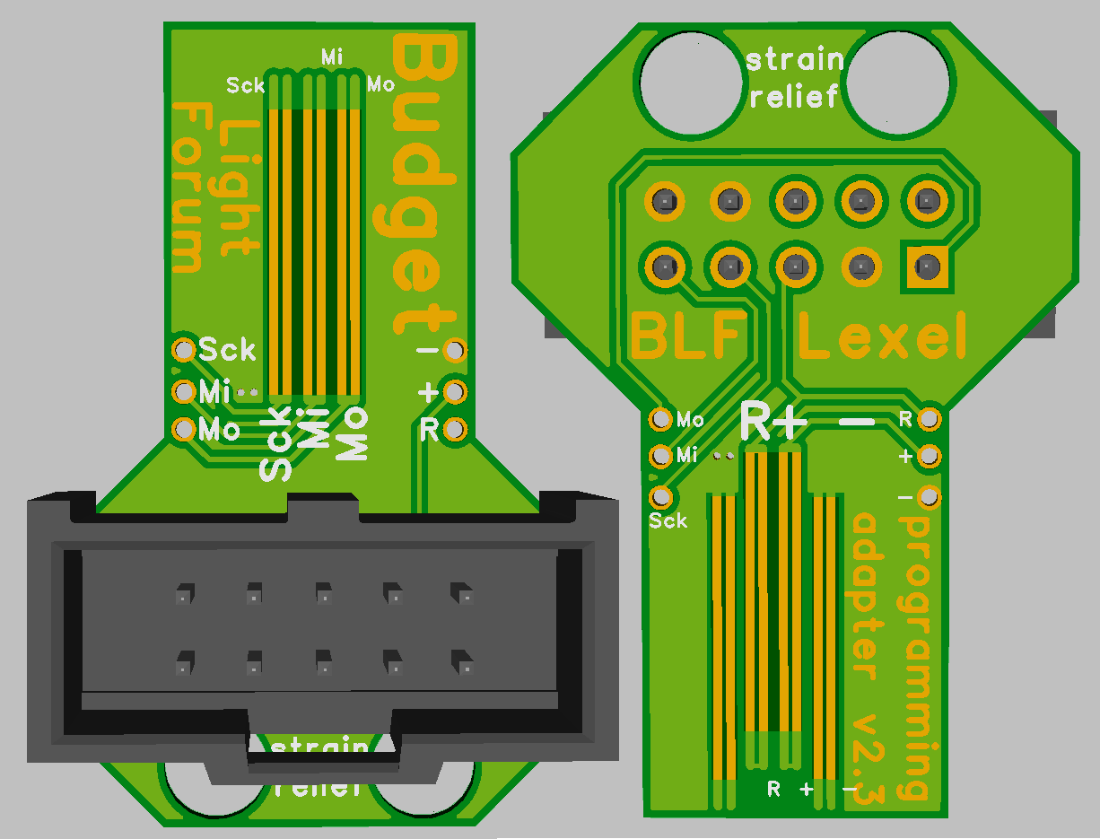
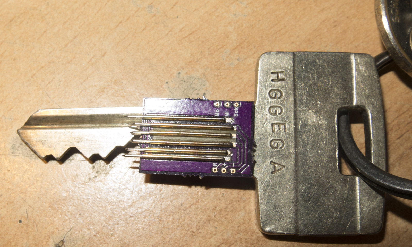
Now, my idea is to combine the USBasp functionality with the AVR re-setter into one MCU and build the whole thing into the key. One MCU, already connected through the six pins. An exercise for someone to combine the code.

Driver designers might have to step up to the mark regarding circuit design, but it doesn’t look particularly difficult. Nor should it add to the cost, except for maybe one transistor and a few Rs. Even if very few ever use it, it could prevent many problems for developers, who may not have the skill, equipment, time or enthusiasm to de-solder, somehow connect (forget clips, decent MCUs are going/already leadless), flash, re-solder, try again. Better than tossing the driver.

Just throwing out these ideas in the hopes that a few might get some traction. This doesn’t have to all be done at once, just the 6 pin plain ISP 50/1000” connection will be a great start.

Integrating everything including HVSP is doable but far too much development work for the limited field of application in my eyes.

I think it’s easier to keep the board with the pogo pins separated and use a connector with the same pinout as the USB ASP programmers, so they can easily get connected without problems. With some (small) drivers a different pogo pin layout might be necessary due to space restrictions, a separate pogo pin board would here be better as well.

so is HVSP is just 12V to the reset pin thats easy accessable on the key using the R pin, just on your USB stick you got to disconnect 5V

Basically all BLF driver designs have reset pin of the MCU insulated anyways
Most drivers have a shottky diode on Vcc so you do not have to bother powering up the rest of the driver

Last 7 days in Hospital I worked on Lantern driver

Feedback put in the latest version, I made it a bit shorter, but added one additional aligning pogo pin pad

the USBasp header is optional, of course a 90° version might be also a good idea, depends what you equip

The USBasp header looks like a nice finger pad.

Would it be possible to add a solder pad for pin one in case someone wants to use it for something one day?

There is a device for arduino users that should make fuse resetting easy. I haven’t looked at it too closely but it includes the source code.

What is the reason for the programming key? Is the programming clip unreliable or using up too much board space?

IIRC, the ‘reason’ for this is to design future drivers to make use of this for convenience. No more fussy clips (maybe not all are fussy, but some are) and sometimes the MCU is legless, so a clip would be useless. Then there’s the access. Using a design like this makes it easier to flash while the driver is still installed in the device. That’s another point for convenience. There are already some drivers that feature vias for pogo pins so that the driver can be re-flashed. So, the idea was already there before this key was made. But, the key will make it easier for drivers that are designed to make use of it.