A “linear” lighted tail-cap is simple. All you need is a bleeder resistor on the main driver (sometimes ) and maybe a little circuitry on the tail PCB to “regulate” power to the tail-cap LED (s). In fact, we already have a few designs around here, that have been tested and work really well. Even one design went into a BLF special light, and is now sold separately on BangGood. Potentiometers have already been used, as well as tiny DIP switches, on some designs as well.
What I’m saying is that while he could make a gchart edition “linear” lighted tail-cap, there wouldn’t be much (anything?) new he could bring to the world by doing so.
DavidEF, the common illuminated tailcaps (such as those going into the BLF X6) used a simple resistor (or potentiometer) to control the current. While the change is small, the current (and therefore the brightness) will decrease as the cell depletes and the voltage drops. Using an LDO in this case will provide a consistent voltage and therefore consistent brightness throughout the useable range of a Li-Ion cell.
With a traditional illuminated tailcap using just a resistor and LED (s), assuming a LED vF of 2.5V and a 15000 Ohm resistor…
At 4.2V, current would be 0.11 mA
At 3.5V, current would be 0.07 mA
At 2.8V, current would be 0.02 mA
If you used an LDO that regulated voltage to 2.8V and then used a 3000 Ohm resistor, you’d get a consistent 0.1 mA draw across the entire range of 4.2V - 2.8V
hopefully I did the maths right… I’m not an EE guy
You’re correct! I just found that Lexel indeed tested a version with a voltage regulator back in February (link). It looks like a few people expressed interest, but then all went quiet.
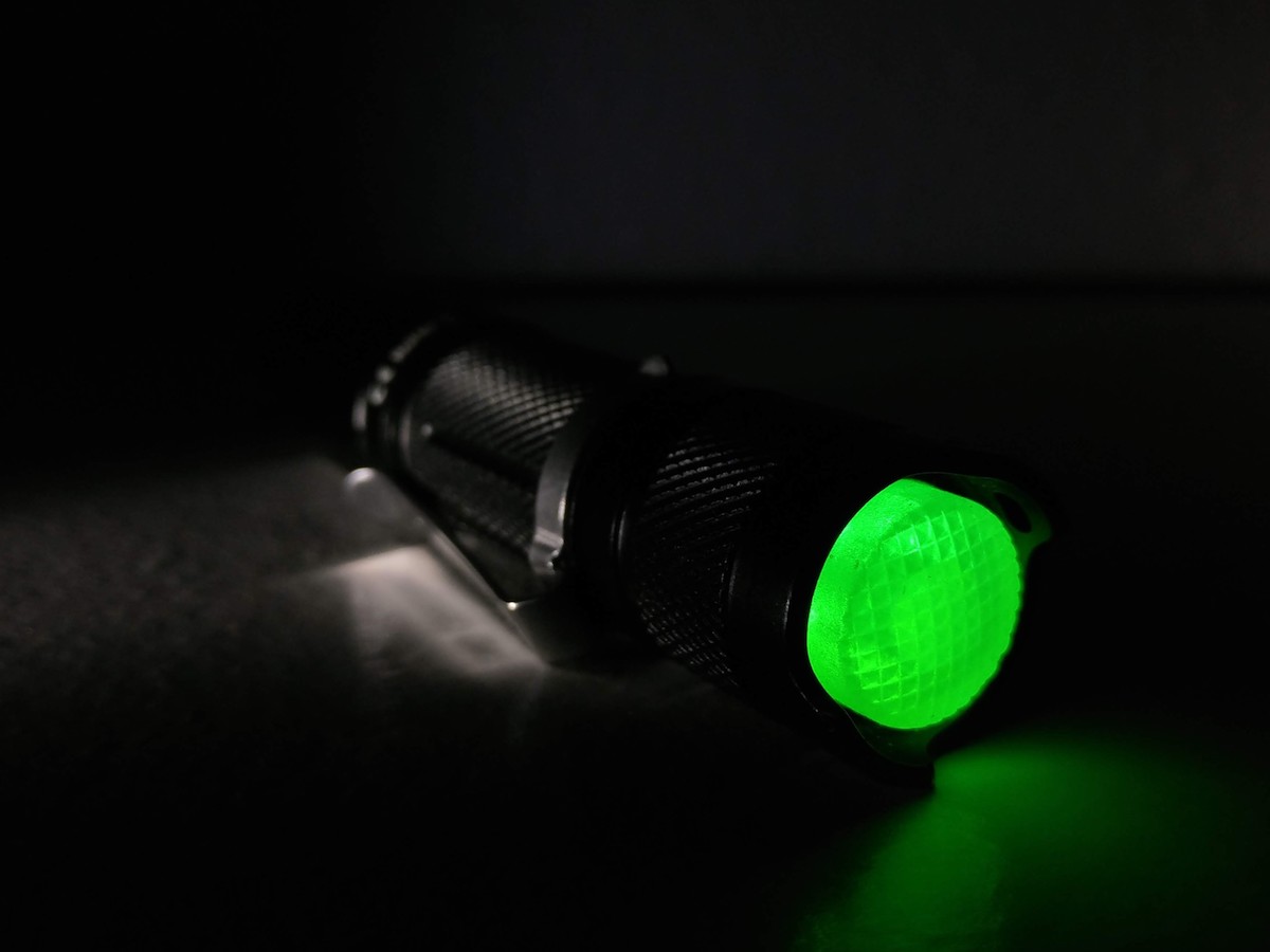
A while ago I did a Sofirn SF14 in green. BTW, a 14x8mm switch cover fits without any modifications.
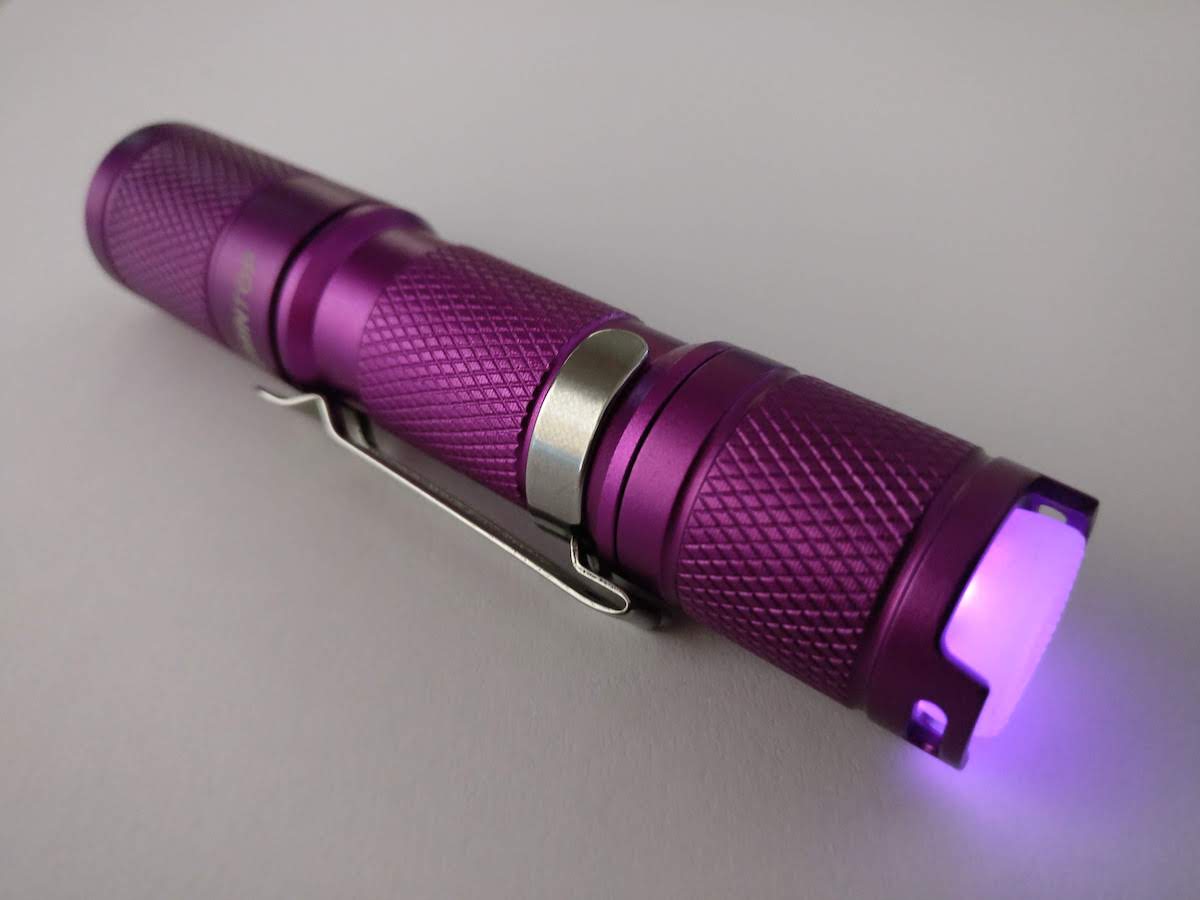
And then about two weeks I assembled a Lumintop Tool AA (purple) for the wife using pink LEDs. The stock switch cover seems to be 12x5.5mm which I couldn’t find in transparent silicone. I ended up buying these 14x6mm ones and reamed out the hole a bit.
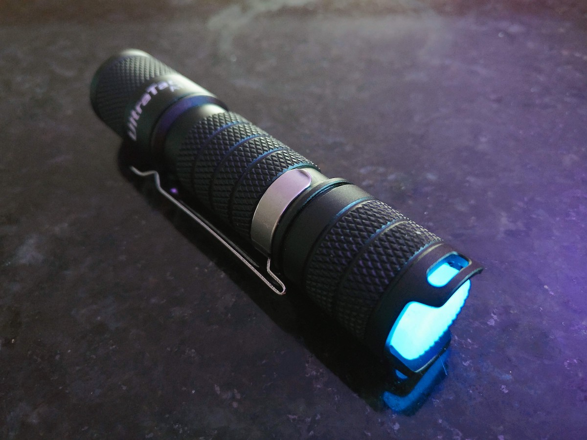
Last night I put one in my new Ultratac A1, using ice blue this time. The switch cover was the same as on the Tool AA, so I had to ream it out as well.
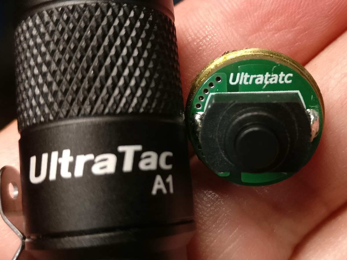
And I noticed the A1 had a nice switchboard, but someone made an embarrassing mistake… :person_facepalming:
I bought it from Banggood (using a coupon from Martin) less than two months ago, but sadly they appear to be out of stock now.
It looks like the official Lumintop store on AliExpress has them for $19.19, but will supposedly drop to $17.75 in 5 days. That’s about what I paid for mine.
Really great to see you have solved the problem gchart. I ordered some 1.4 boards and parts.
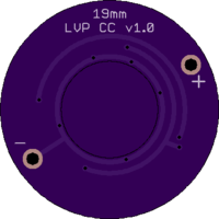
Life got in the way and I finally attempted a v1.0 just today. Used 130K resister and just one LED channel. Worked great on the bench. Seemed to work fine in a Tank007 with a 14500. With a Nimh, the taillights would stay lit for a few seconds and then turn off. The driver seemed to work fine in both cases. I didn't try any workarounds as your low-current booster solution sounds like the best way to go.
Thanks! I’ve been really pleased with the v1.4 boards and how the lights have turned out.
The only strange thing I’ve encountered lately is that mode switching with the Ultratac A1 has issues on NiMH: if the tap isn’t ultra-fast, the light flashes the higher mode and then kicks back to low. My theory is that LVP is recognizing the boosted voltage as a Li-Ion for an instant, then sees the voltage drop down and kicks it back to low. Just a guess. Works perfectly on Li-Ion though (which kinda defeats the purpose of a boost circuit, of course).
As you’ve found out with the Tank007, it seems like each of these dual-voltage drivers have their own nuances. So far, both the Sofirn SF14 and Tool AA have worked great.
I haven’t seen the behavior you’ve described. When that happens, does the main LED illuminate dimly?
Not that I can see. I suspect that, on NiMh, the driver is not leaking enough current to run the tail circuit. I bet a bleeder resistor would fix the issue. I might try that since it looks like the v1.0 might work in this light.
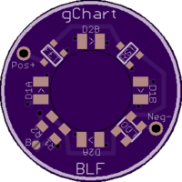
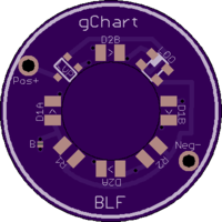
I’ve got a new tailcap design with consistent brightness and LVP with minimal additional components. Brief post and video demo about it here, I’ll do a write-up shortly.
That’s great, Nick! Did you use reflow for the boost side, or an iron? I would imagine it’d be extremely difficult with an iron on that WSON package. Using solder paste and a hotplate (or even a skillet) is pretty do-able.
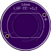
This board uses a Voltage Reset Monitor to provide LVP and an LDO to provide a constant voltage (an in effect, constant current). Everything is on a single side for quick & easy reflow soldering. It’s dual-channel, but includes a Bridge pad for making it single-channel.
LVP: MAX809SQ293D1T1G, a 2.93V active-low Voltage Reset Monitor with 0.5uA quiescent current
LDO: NCP553SQ30T1G, a 3V “NoCap” LDO with a 2.8uA quiescent current (typical)
FET: PFET, size SC-70 / SOT-323 (such as BSS209PWH6327XTSA1) or NTS2101PT1G
LEDs: 0805 size
Resistors: 0603 size
So altogether, there should be a total quiescent current of around 3.3uA while the tailcap is lit, going down to 0.5uA after LVP trips. In comparison to the current for the LEDs (typically 0.15mA = 150uA or higher, this is absolutely minimal)
Such exciting stuff going on here. I have all the stuff to build you latest design (before the above), but big lights have been winning out on my attention for some time now. Looking forward to building some of your awesome tail lights eventually. Thank you for sharing your designs and expertise with us. :)