I can’t remember exactly what value I changed it to but the first time I changed the divider value the driver would run down to 2.4V on a bench power supply but at a very low current. So the boost IC will work at a lower than rated voltage.
I believe you meant “R12 is below the capacitor and R11 is below R12, with the trace running to the spring”.
Thanks, this means the divider is now set with 100KΩ resistors, and much easier to access. Thank O:) God.
Cheers ^:)
Yeah in the schematic R11 and R12. Usually in a voltage divider there labeled R1 and R2. You got it figured out though. ![]() Being on the battery side of the driver does make it very convenient :+1:
Being on the battery side of the driver does make it very convenient :+1:
It looks like an Attiny programmed for the GT should plug right in place of the PIC with the right adapter board.
The ones in this thread will not work. here is the LD-29 MCU pinout (eg how to put your ATtiny13A in there...)
Are there more boards around here somewhere?
Where does the switch connect to?
What's wrong with PIC microcontrollers?
PIC microcontrollers are widespread among lots of great drivers. The existing disregard against these microcontrollers is odd to me, it is sort of like swimming against the tide. Porting the high level language code among them should not be hard. ![]()
Cheers ^:)
I don’t think anyone here cares about the name on the chip, it’s the program inside.
If you can point me to a pic program as good as Bistro, Narsil or Anduril I’d greatly appreciate it.
I’ve tried porting Anduril to an Attiny 1634 and failed. I’m not even going to try moving it onto a pic.
As far as I understand, you're programming in high level language. High level languages plus compilers is what allows developers to port Android into diverse architectures without much hassle, something also done over the years by multi-platform game developers. I am not saying it is challenge free. ![]()
Here we are dealing with easy as a pie architectures, though. Both ATtiny25 and PIC12F683 are 8-bit microcontrollers with 2KB of flash, 128 bytes of SRAM and 128/256 bytes of EEPROM. Porting from ATtiny25 to PIC12F683 should be pretty straightforward.
By the way, I neither Bistro, Narsil nor Anduril, and this is not my war. But I believe you're restricting yourselves too much, and the driver technology you're making use of is just bollocksy outdated (AMC7135s). HKJ will soon publish a review of a variable output linear driver without PWM.
Cheers ^:)
[quote=Barkuti]
HJK has already tested such a driver , one of the early LDx drivers. They are cheap and work great. I don’t see how such a Chinese driver is going to be better.
It’s not so easy because Narsil/Andruil use a lot of hardware-specific idioms. Doable, but definitely not straightforward.
You mean it has a lot of low level optimizations. Go assembler :-D then.
Initial stripped down versions of the software are not necessarily bad. If a full port initially seems overwhelming, the problematic functions and related code parts can be removed and still attain a better than whatever is available thing, which is good. This would also serve to start rotating the development wheel. Just an opinion.
![]()
Optimizations? Not sure. I meant hardware access. Sleep mode, timers etc.
There are quite a few changes to be made. I’m mostly C illiterate and thought it would be a good learning experience. The clock prescale part wasn’t too bad but I got bogged down in the pwm changes. Once I realized I was just hacking and not learning I quit. The changes would be easy for Toykeeper but at this point I would be better served writing my own program in Arduino.
Everyone has their own priorities. I barely ever notice pwm but I notice a bad user interface every time I use a light. And the light with this driver in it stays in the glove box of my car because of it.


With regards to the R11/R12 low voltage protection divider, I have a couple of right sized 300KΩ resistors from a couple donor drivers. If I stack one of those over R11, the divider would change to 75KΩ/100KΩ, for a resulting VLVP of 2.625V, a little bit below TPS61088's minimum input voltage (2.7V).
Should I concern about this? 
Not that driver, but this 3A 3-mode (plus hidden strobe) unit at FastTech. It costs less than €4, thus I find it is nice and cheap.
Cheers ^:)
Originally posted on Tue, 08/28/2018 - 20:15. Edited for fixes.
When I was testing the H1-A using a power supply it ran all the way down to 2.4v before it shut off, so I would say your fine.
Thanks for the reply, moderator007. I have an H1-A already modified for 4.5A output. Based on jensen567's 2.82A measured stock output, I consider this to be around the maximum effective current this driver can output at 2S XHP50A voltage (≈4.23A effective). Right now I'm just wondering if I should bypass the reverse polarity protection transistor, to help with TPS61088's cooling. 
Cheers ^:)
Did the thing survived for long?
I am wondering…

… if sticking on the inductor case atop the boost IC would somewhat help with cooling, it is an easy thing to do just by desoldering its terminals, putting a dab of thermal paste/glue on top of the TPS61088, setting the thing on top and resoldering. Well, maybe a copper shim would be required.
Cheers :-)
The one thing you could do is stick a very small thermal adhesive dab on it, and then put a small copper shim on it.
Would help a lot.
Hi fellows! Just had a mishap while setting up one of my H1-As, shattered capacitor C11, the one attached to MCU's pin 8. Lost one of its leads. I've sort of managed to have a readout of its capacity with my multimeter, got from 25 to close to 33nF max. If someone is able to tell me what could be its capacitance value and post it here, that would be of help. I've tried to measure it over the glue on a spare driver but the measurement bounces up  and down without end. Thanks.
Cheers ^:)
Mmm, just found something interesting in the newer Kaidomain H1-A drivers, there's no need to modify the output voltage divider for 3/4S emitters:
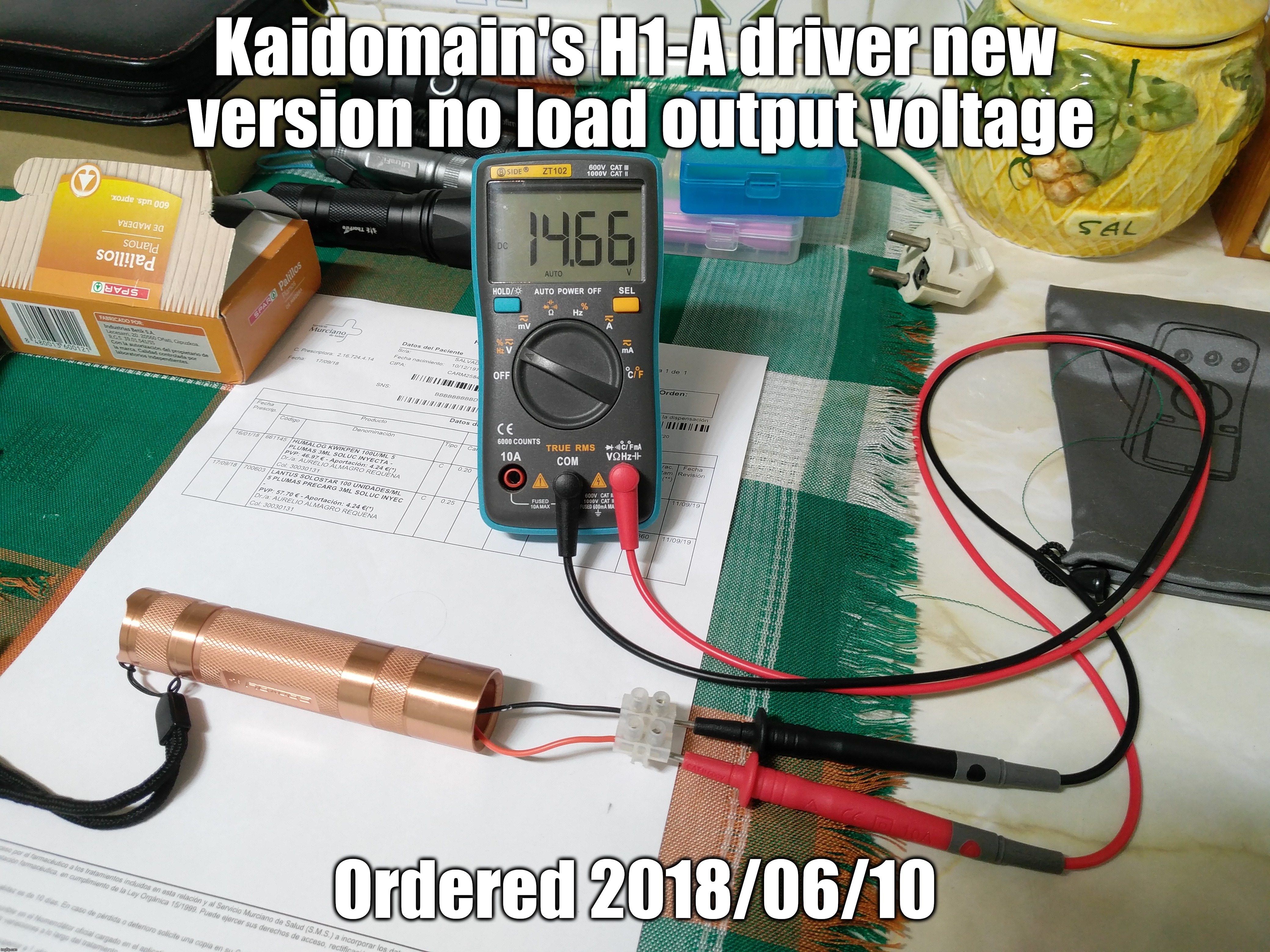
Looks like you can even drive XHP35s as it comes now, although in such a case I'd limit the current output to no more than 2A at most. That would already be ≈27.5W of power to the emitter, and driver's efficiency when boosting 3.x volts to nearly 14V is probably going to suck a bit, thus watch out for driver's temperature. With stock R025 output is 3A, swap it for an R050 for 1.5A max. R050 + R200 is 1.875A (75mV sense voltage). ![]()
Cheers :-)
News!
After lowering the R11/R12 low voltage protection divider to 2.625V by stacking a 300KΩ resistor on top of R11, I noticed no usual low voltage warning in my modified SK98, at some point its output started to twitch and wouldn't change to the higher modes. I guess this is because the micro controller unit cannot work well with such a low battery voltage since it is fed via 2.8V LDO1. :-)
Measured cell voltage 2.72 - 2.73V once I arrived home, so it sort :-D of works LoL.
Cheers ^:)