Thanks for the reminder; done!
Cool idea! :+1:
Subscribed to see how this proceeds. ![]()
Looks cool!
Sounds like you have a plan. ![]()
Maybe you could fit in one of those little usb chargers as well?
Ok, I’m back in my box. ![]()
subscribed because its a lantern build! ![]()
I like the idea (a TP4056?). I dunno if it’ll fit well into the design, but I’ll definitely keep it in mind if it looks like it’ll fit!
Nice idea, looking forward to watching the progress.
You are the man, to do this that is. ![]()
Do many LEDs in parallel, so they all get a smaller bit of current, that way you get much higher lumens/W and you can get longer runtime ![]()
Ingenious ![]()
Love the tilt idea, though some kind of lockout would be useful. ![]()
Subscribed.
Good luck!
Have any of you tried PCBWay or AllPCB for your PCBs? I’m leaning towards PCBWay for this project. I always use Oshpark but I’m looking to get ones with white solder mask. They’re both in China, but seem to have good prices, lots of options, and pretty quick turn around time.
Cant help you there. I’ve only used Oshpark.
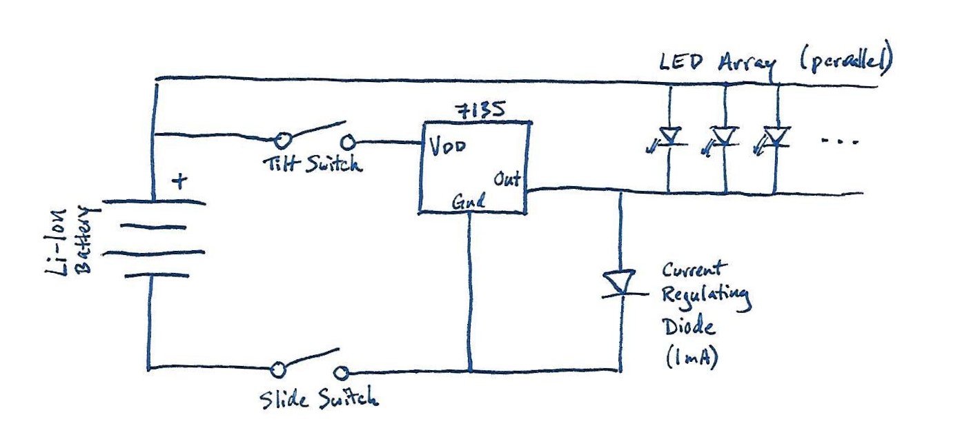
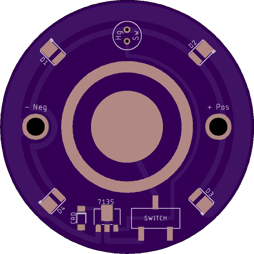
Ok, I’m still learning about proper driver designs, so I’m going to throw my schematic and PCB out here for critique before I order it. The PCB has been uploaded to Oshpark, but I will likely be using a different service (see above).
https://oshpark.com/shared_projects/zMUnQFCd

Another note… I decided to simplify a bit and spec out a Current Regulating Diode (1ma version) in place of the LDO+resistor. I’ve never seen one used but they appear pretty basic.
Oh, another thing… While this is one board, I’m basically designing it as if they were two separate ones, the circuitry is independent of each other. One side will be used as the main board of the lantern while the other will be a slave board.
Why is there a ring around the center pad? What purpose does it serve?
Looking at your schematic. Can you describe to me in words how you expect it to function? I’m having a hard time trying to understand it. :person_facepalming:
EDIT: In particular, the switching doesn’t make sense to me. I understand the slide switch disconnects the ground and turns the light off, but what is the tilt switch supposed to accomplish?
Hey David!
- Ring around battery pads: my plan for holding the battery in place is to have a ring of 3/4” copper pipe (perhaps 1/2” tall) attached to the top of each board with just enough of a gap that the battery can be slid into position and then be held by the spring on the neg pad. The exposed ring on the PCB will allow me to solder the copper pipe pieces in place.
- Switches: the slide switch, as you said, will disconnect the ground and completely disable the lantern. When that’s switched on, the mercury (Hg) switch will turn the 7135 on or off.
- Functionality: When the primary board is face up, the mercury switch will be On, enabling the 7135 and pushing 350mA through the LEDs. When you physically flip the lantern over, the mercury switch will turn the 7135 off. However, current will still be able to flow through the Current Regulating Diode (Semitec S-102T) sending 1mA to the LEDs for a dim glow (akin to the illuminated tailcaps I’m so fond of
 ). I am debating, however, if 1mA might be too bright. Most of my tailcaps operate at around ~0.15mA, but then again, this lantern is much larger than a tailcap.
OK, I get it now, the two power deliveries are wired parallel to the LEDs. Either just the 1mA source or that plus the 7135 will be on. :+1:
Yup!