Nice, will have to give it a try. In the comparison photo above, is the Tube on default-at-first-click Low or High? The brightness difference would indicate that the Yuji is many times more efficient than the OEM.
Oh how I wish it was. In that pic the stock Tube is ramped up about half way just to match the brightness of the Yuji Tube which was on at full power so I could get a good picture of the tint difference. My Yuji emitter is being run at about 25mA while the stock emitter is run at about 100mA, so it’s got substantially less output. But the tint is SO much easier on the eyes.
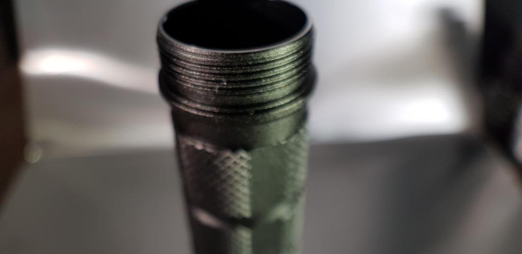
Now that the tube was clampt in a big vise it was almost to easy to open. But cleaning the threads was a pain in the A…
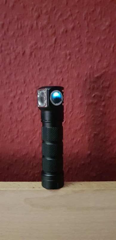
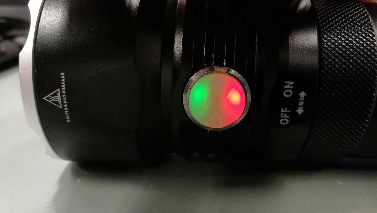
I wanted to install 3 ice blue leds behind the TIR. I had them soldert together and glued to a strip of GITD tape. But i put the leds to high up on the strip. And when i installed the TIR i noticed that i did not have enough space. But that was enough for today. So i went only with the one led that is original at the switch (but changed the red one to ice blue). I love Narsil in my H03!!! Puts out a lot more light/heat at turbo. But its nice to have another light with this awesome UI!!! All wires are silikone wire, Led wire is 20AWG switch wires 30awg. I have to think about the tail spring. At the moment this is the point where i can gain the most. But it is already way to much power for such a small and lightweight host.
Maybe tomorrow i will try to put the 3 additional leds (behind the TIR) in again.
Must be a good day with very stady hands. To solder 0603 leds on a pcb thats easy but to solder them in a free configuration to a 0,1mm copper wire + the resistors. No that is requiring a very good day.
Oh well, better tint is still a good reason for swapping. I might play with resistor and push to 50mA.
Thanks.
Dale,
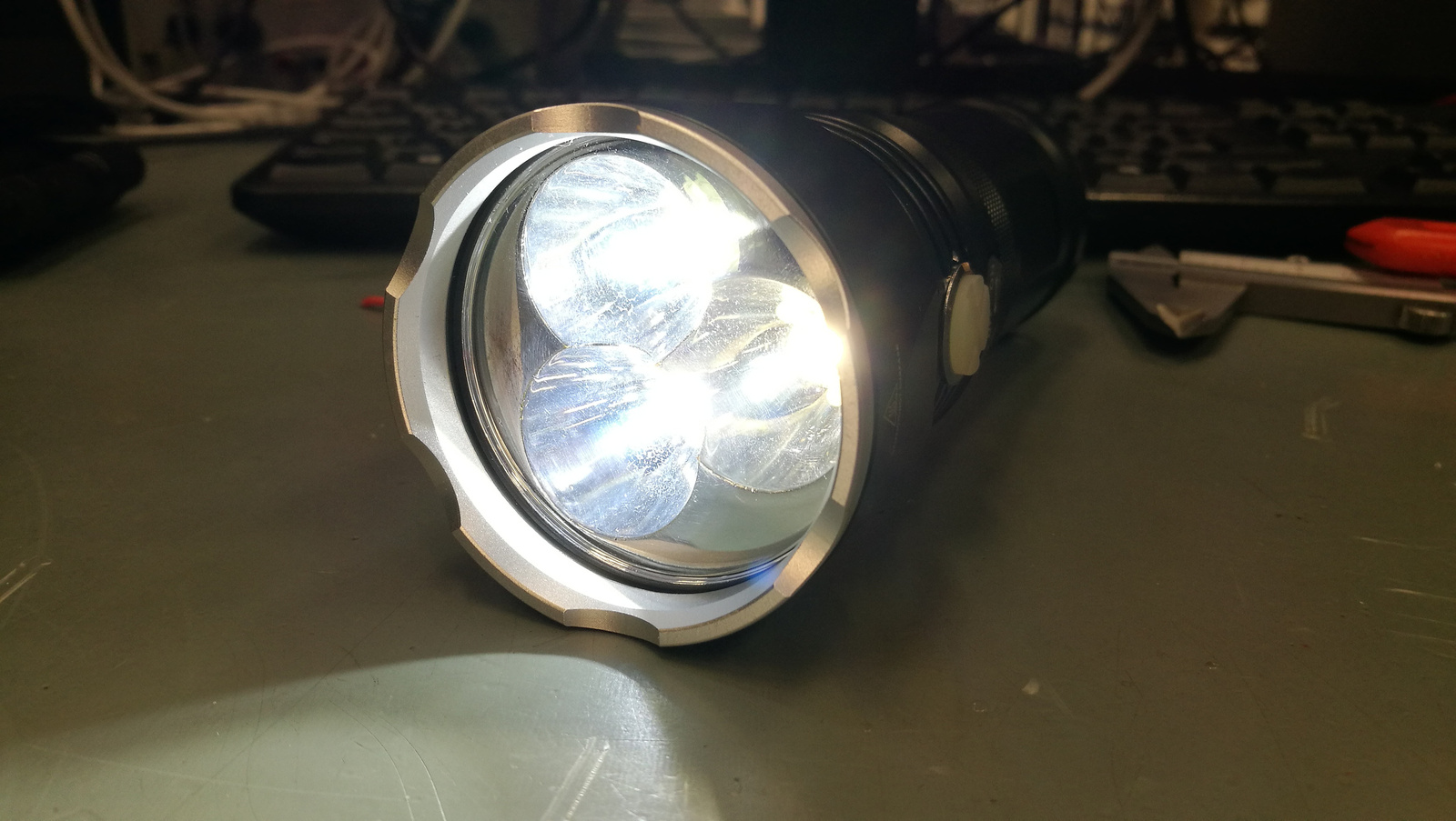
You were right, as usual. I made a huge mess with thermal paste and screwed it back in. It was way easier to screw in after cleaning the threads and using paste. It’s a pretty noticeable difference. The head will get warm now and the light is maintaining 2-3x more output than before so thanks for that.
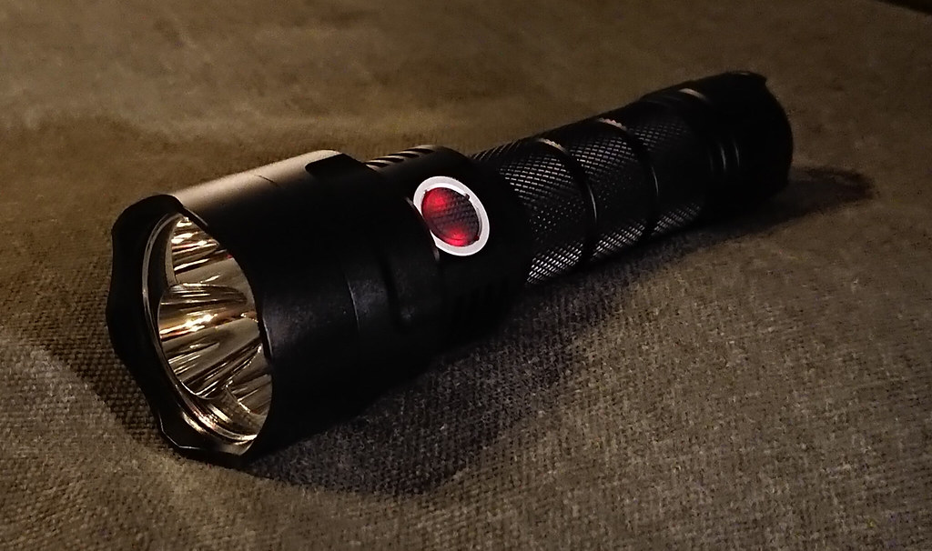
Same glamour shots below. It’s oven baked and I swapped the switch boot with a clear one.


Glad that helped, nice bake job! ![]()
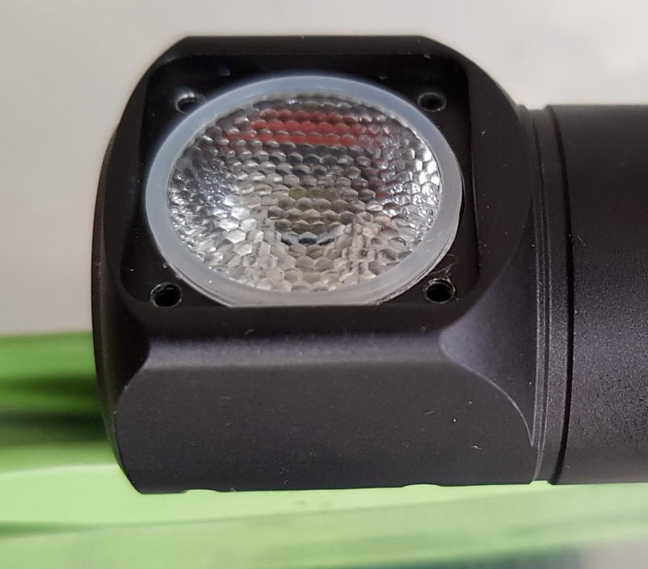
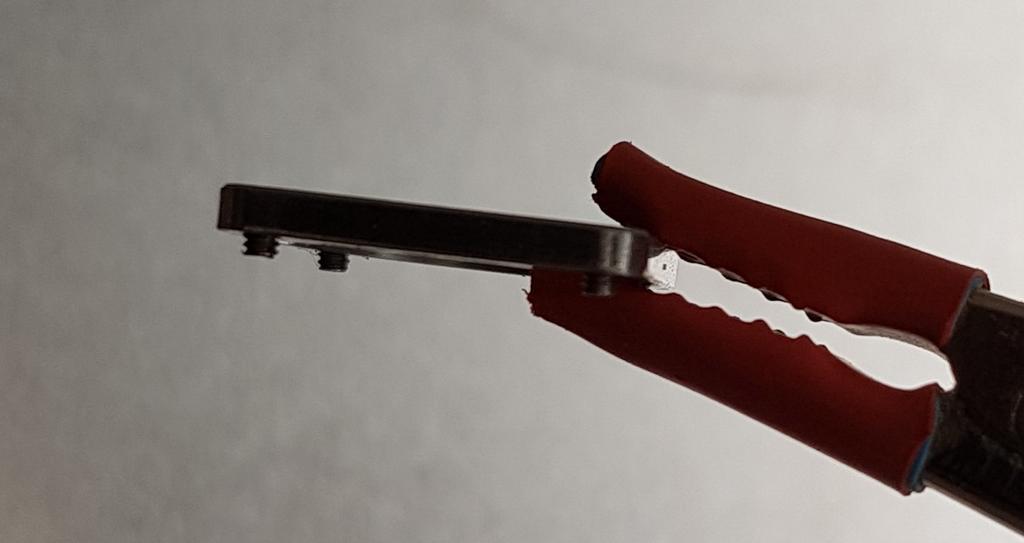
The new TIR back light is ready and works fine. Only problem now is a stripped thread. The original screws are M1,6*2.5mm. Extreme short! On the front SS frame you loose 1mm and at the o-ring another bit. So the srew was only in with 1/2- 3/4 turn. I ordered a few A2 1,6*4mm screws. Will have to grind the screw head a little bit (3mm to 2,5mm). But i have to wait 2-3 days for the package.
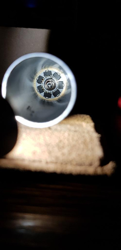
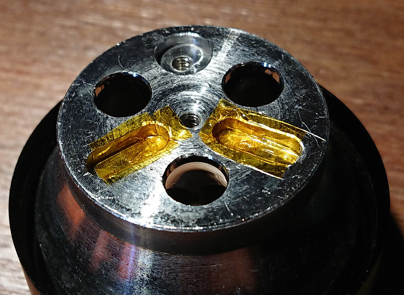
On the picture you see two strips of copper foil (what you use for making Tiffany glass art) on Kapton tape. Next i soldert the leds to the foil added the leads and covert it with UV resin. Then cut it out with scissors and glued it inside the head. On the picture is the light without the Stainless Steel frame. The color is more ice blue with a glimmer of purple/pink if you see it in real. And it is more dimm in real. Also i disconnected the switch led so only the TIR backlight is connected with the Switchled output from the driver (NarsilM).


Update.
Not happy with the build quality from Skillhunt. Trying to screw in a longer srew was not possible because there is no thread in the holes. Only at the first mm (i think instead of cutting a thread into the holes they screwd the SS screws directly into the holes). But with the slightly longer ones this is not going to work. So i ordered a set of 3 M1,6 threadcutters. That should not be a problem with a light in this class.
It’s not so much a matter of the class of light, but a parameter set by it’s designers. They saw no need for longer threads, they made the light fit their design… that is all. Some of these guys are seriously OCD, they probably thought it was a fine matter of paying attention to detail, only making the threads as long as they Absolutely Had to be…
When you mod lights, you acquire tools to do so. You simply would not believe the stacks of flashlight related bits I have over here!
I have a lot of threadcutters. But not the 1,6mm i need. And i forgot how expensive they are (if you want to buy the good stuff).
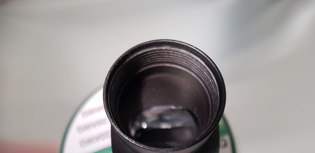
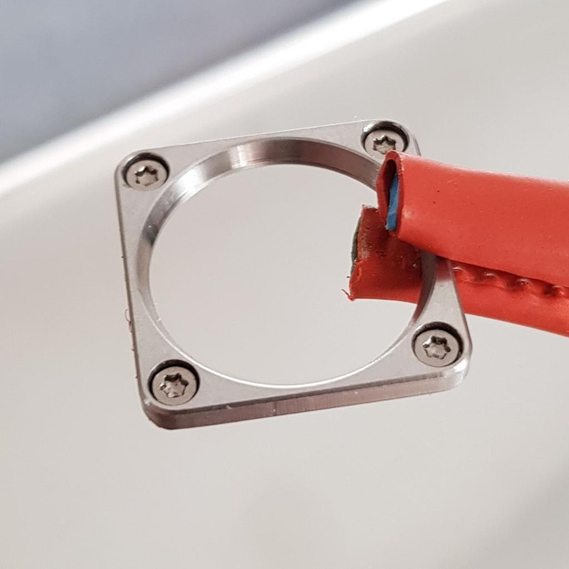
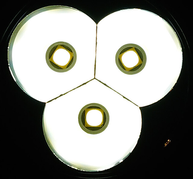
Here are a few pictures of the head (so you can see how far the oring is standing over the edge). And a picture of the frame with the original screws. Not much to work with. I had hoped that they cut the threads with a threadcutter not with the SS screw. But that will be fixed soon! I really like the TIR backlight! Wanted to do this for a long time!
Sheesh! That’s cutting it awfully close!
In a pinch you can take the longer screw and cut a groove down each side of the screw with a thin dremel type cutting disc. This works especially well with harden screws and threading into softer metals like aluminum. Don’t go to deep with the grooves though and take your time reversing direction when tight or the screw will break off. Nice job TheOnlyDocc :+1:
Great work Docc! I like the way you fabricated the background leds. ![]()
Today I had my go on the new Sofirn C8F 21700 version. Tried to stretch it to the max.
I already have a C8F 18650 version with Luxeon V leds that does a bit over 3000 lumen (30Q 30sec).edit: those were not Luxeon V’s but XP-L2 4000K 80 CRI. These are the new honest-BLF-lumens by the way, the djozz-lumen corrected as well as I could to maukka’s calibration.
What do Luxeon V’s do in the 21700 version?
I like the looks of the 21700 C8 much better than the classic C8, the bigger battery tube makes it a bit more mean-looking ![]() And just like the 18650 version the host version comes without any branding :+1: .
And just like the 18650 version the host version comes without any branding :+1: .
I have just one build picture, the rest:
*reflowed the Luxeon V’s (from L4P) on the stock MCPCB and soldered long enough 18AWG wire to be able go through the head and solder to the driver on the other side (7cm?).
*I Kapton-taped the cavities in the reflector for the led-wires. If they ever unsolder themselves they will not easily short against the reflector.
*I did something unethical: Neal had sent me a spare driver for the mini-GT because I had a faulty switch. In the meantime the switch started functioning again so although I should keep the driver in case the switch fails again, I could not resist using it for this mod :person_facepalming:
So I sanded the 22mm mini-GT driver to 21mm, and removed the switch and switch-led from the driver. I filed corners off the 7135 chip and the FET to make them fit inside the driver cavity rim (which is rather wide unfortunately) and taped a strip of Kapton tape around the side of the driver to prevent components to short with that rim. Batt- contact is via the driver retaining ring.
*I soldered a very short spring on the driver with 20 AWG bypass (very well attached!) on the outside to allow it to go as flat as possible (this host is hardly long enough for a 21700 battery)
*the tail spring was also made shorter and was bypassed as well. I like the big 6A rated (but can handle much more) switch that Sofirn has chosen for this light.
*I bought especially for this project an expensive Vapcell 3100mAh 35A-rated 21700 cell (fron Nkon). (Samsung 30T inside)

So now the light looked good but this is about output: 5250 lm at 3 seconds, 4800 lm at 30 seconds (again honest BLF lumens). I measure 23 amps with tail off and clamp meter, so on a full battery the leds are driven pretty close the max.
I adjusted the stepdown temperature to 70degC measured on the outside of the head (so hot that the switch-off was best done with the tail clicky) and it takes 105 seconds for the stepdown to kick in (longer while the battery drains). I think I will go back to 60degC ![]()
Modded a Solarstorm T3 with dust collecting parts from shelf.
Triple XP-L HI with fet+1 driver and Andúril firmware.
Build thread here.
Nice powerpackage djozz. Thats almost the same current my Q8 is reaching. I saw this C8 tripple dtp board a few days ago and wanted to ask you if it could be a candidate for replacing the F3X board. I kow its bigger but if the led spacing is ok i can grind it down (will be a pain in the A… to prevent shorts)
It is more current than the Q8 actually, stock the Q8 draws about 16A, with bypasses it goes over 20A. But in the Q8 the current is divided over 4 leds so the leds are running in a more efficient region so the output is better. And at 23A my 3100mAh battery is drained in 8 minutes. If I have some new money to spend on the hobby (I’m broke atm) I will check a Samsung 40T, it delivers a bit less current produces a bit less heat and more runtime, at almost the same output.
Djozz, you changed the emmiters for Samsung LH351D in Q8, right? I really like the tint of 351D 4000K a lot.
How much does the flashlight draw, did you make a measurement? I am consider this MOD, but i little worry about life of leds considering a low vf. I only use 30Q button top cells in Q8, no more oprikns for me this way.
My Q8 is in stock form, no bypassed springs. I might to solder a longer awg22 wires from driver to the leds as way to lower a current.
What is your experience?
I did not worry about the lifetime of the LH351D (did not measure the current), it can handle a lot of current but if you worry about it you could stick to 16A current, which indeed may imply that no springs are bypassed and perhaps use longer and 20AWG ledwires instead of 18.
I will measure the current when I’m home tonight.
Thanks, it will be intersting to compare the current with stock Q8.
You can get your branding here:
The fablab in Amsterdam has a laser cutter / engraver.
You can label it e.g. djozz-fire ![]()
:laughing: Sofirn should have kept the flat bits on the battery tube for my djozzfire branding, I can use one of my old pictures for a logo:
