Looking at your schematic. Can you describe to me in words how you expect it to function? I’m having a hard time trying to understand it. :person_facepalming:
EDIT: In particular, the switching doesn’t make sense to me. I understand the slide switch disconnects the ground and turns the light off, but what is the tilt switch supposed to accomplish?
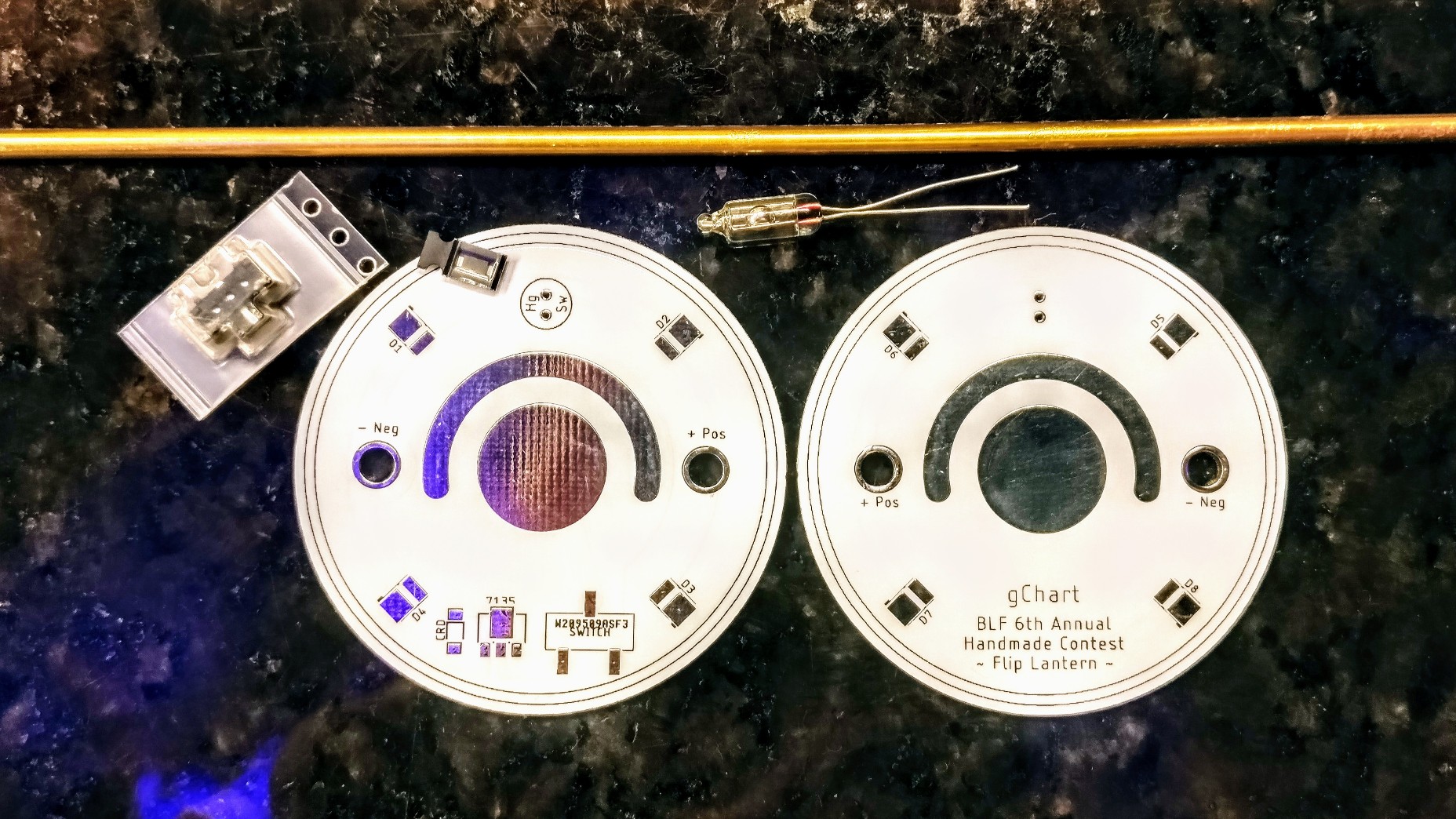
Ring around battery pads: my plan for holding the battery in place is to have a ring of 3/4” copper pipe (perhaps 1/2” tall) attached to the top of each board with just enough of a gap that the battery can be slid into position and then be held by the spring on the neg pad. The exposed ring on the PCB will allow me to solder the copper pipe pieces in place.
Switches: the slide switch, as you said, will disconnect the ground and completely disable the lantern. When that’s switched on, the mercury (Hg) switch will turn the 7135 on or off.
Functionality: When the primary board is face up, the mercury switch will be On, enabling the 7135 and pushing 350mA through the LEDs. When you physically flip the lantern over, the mercury switch will turn the 7135 off. However, current will still be able to flow through the Current Regulating Diode (Semitec S-102T) sending 1mA to the LEDs for a dim glow (akin to the illuminated tailcaps I’m so fond of ). I am debating, however, if 1mA might be too bright. Most of my tailcaps operate at around ~0.15mA, but then again, this lantern is much larger than a tailcap.
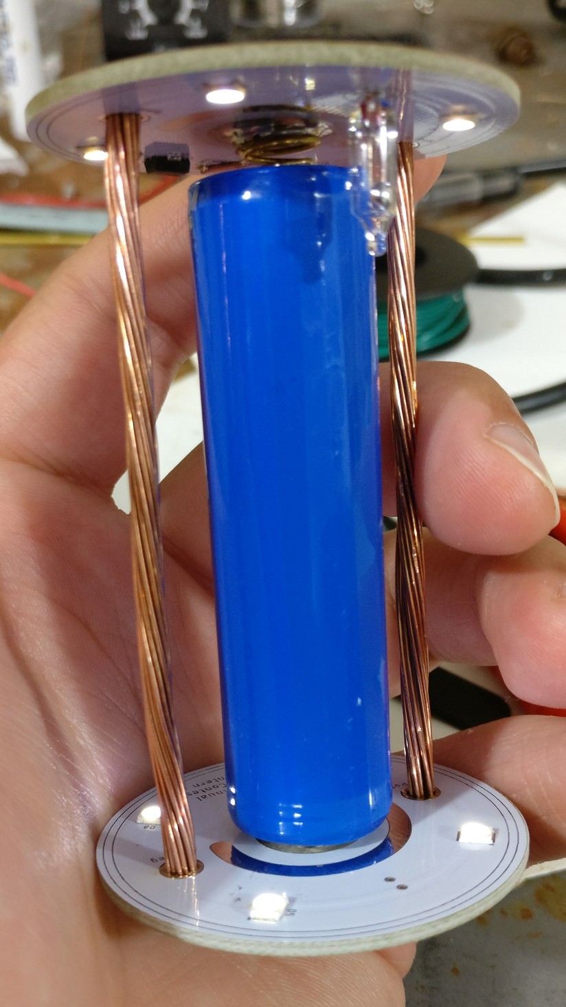
Even though my 4000K LEDs aren’t in yet, I couldn’t help but build a prototype while I wait! I have some 5000K on hand, so I used those - I just wanted something warmer for a “lantern” style device.
Differences between this light engine and what I have envisioned for the final version:
5000K LEDs instead of 4000K
Used a 1800 Ohm resistor instead of the 1mA current regulating diode. Assuming a supply voltage of 4.2V and a LED forward voltage of 2.43V (as measured), that should give me roughly 1mA on a full battery: (4.2V - 2.5V) / 1800 Ohms = 0.00098A = 0.98mA
Jumped the switch pads with a wire instead of a switch (like the CRD, I only bought one switch)
Stranded copper wire for the conductor pillars instead of the copper rods (only bought enough for the final version)
Battery is only held in place by the spring tension. I plan on having a partial copper surround and then a velcro strap or something to make sure it doesn’t budge.
Dim mode, Bright mode .
Action video:
Another tidbit… assuming a 3000 mAh battery, this should last 8.6 hours on high or 4.2 months on low/moonlight.
Ok, I decided to go a different route for the end caps. I was trying to mostly use materials I already had sitting around (putting the B in BLF!), but that oak was hefty to work by hand.
So I picked up a piece of 1/4” poplar. I think I’m going with two stacked discs, one being smaller to fit into the plastic housing, large enough to pressure-fit in place. I’ll glue that to a slightly larger disc that will sit outside of the housing.
Here’s the rough cut with a jigsaw:
And getting to it’s final size & shape using my palm sander:
 .
.