So that's how it works thanks! Would you know for sure if my stock L6 would need one still? I'm still not 100% sure as of this point.
So that's how it works thanks! Would you know for sure if my stock L6 would need one still? I'm still not 100% sure as of this point.
DB, I still don’t think you got my point earlier about each object in the circuit having its own relative positive and negative. (That’s okay) It’s all in how you look at things. I made a picture to better explain it. (I’m going to explain it in simple terms because I know there are many other people reading who are not as familiar with electricity as you are. So don’t be offended.)

This is a simple circuit, not exactly a flashlight, but close enough. The battery always determines positive and negative, no doubt about that.
My point is that each object in the circuit can also be thought of as having its own positive side and negative side. That meter has a positive and negative side, that bulb has a positive and negative side. That switch has a positive and negative side.
As long as the switch is open, electricity does not flow. A lighted tail cap pcb (from Lexel in this example) needs power to work, so how do we power it? We “bypass” the switch. Now the tail cap pcb has leds on it, so polarity is important. We attach little wires from the tail cap pcb positive to the switch “positive”. Then we attach a wire from the tail cap pcb negative to the switch “negative”.

Now the tail cap pcb can power up all those colorful leds. :partying_face:
EDIT II: I’ll be forever dam*ed! I hooked up my bench emitter at the battery tube (red) and end of cell (black) and of course it actually fired up both emitters! Didn’t like it, reduced output and glitching when the driver was in low mode but hey, it does indeed work that way! Never did that before, never had cause to, but the LED wired in as a “switch” does indeed work. Learn something new every day! (will probably forget it by tomorrow…)
Sorry, my bad.
But cutting the negative circuit to install a switch doesn’t give a positive side to it, it’s still negative no matter how you draw it out. Ground it and you have a light on, ground a positive and you have magic smoke!
There is no positive on the switch, you can solder your leads to the switch without orientation, it’s just a break in the negative line…
The only way to get those switch LED’s to light up is to give them both positive and negative leads, you won’t get that from the switch unless there’s a bleeder resistor on the driver. Essentially, a parasite…
Edit: As I understand it, the bleeder resistor is a very small direct short that shunts some positive electrons back into the negative carrier… the battery tube in this case. Thus, the switch when off does indeed have this tiny short circuit backflushing into it which is what is used to power the very lower draw switch led’s. Without this small short circuit, the switch has no positive energy, the normal and proper way for it to work. Just a break in the negative chain. When the light is on the current is so much larger that it overpowers this small short circuit and the switch lights don’t work. When the light is off, the tiny surge of positive electrons once again powers the switch leds. A parasitic drain on the li-ion cell.
I admit to not being an electrical engineer, I don’t necessarily understand how it all works, but I dang sure know how to build em! I’ve got it wrong a few times, sure, but I’ve gotten it really right over 500 times to date… 200+ of those are on the shelves in front of me even now…
Redundant gibberish, again, my bad.
+1 Some drivers will not work without a bleed resistor and some will.
Thanks for the detailed illustration 
The bleeder resistor or LDO acting as such, confuses me still.
Whenever we add some leds across the tail switch we are sending power to the driver, albeit a very small amount.
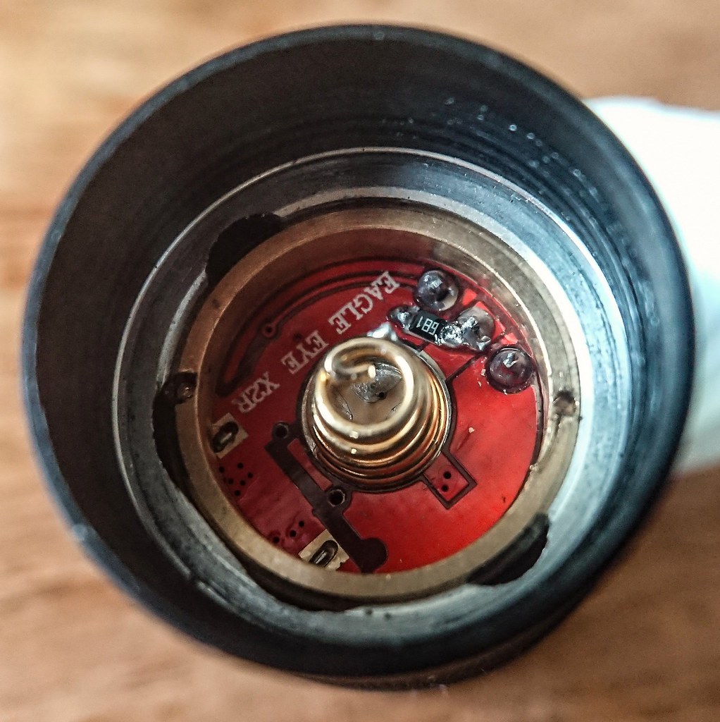
When I added a glowing tail cap light on my Eagle Eye X2R the light works fine in all modes, but it loses its off time memory and operates as if it has next mode memory. I need to add a 680 ohm bleeder resistor to the driver and that’s supposed to make the memory work properly.
This is still one of those flashlight gray areas for me. Pilotdog68 might know more since he built a lot of tail switch led pcb’s.
I THINK, emphasis on think, that the job of the bleeder resistor is to cause the electrical current to bypass the driver which then allows the driver to function normally. The amount of current drawn from the tail cap LEDs needs to be taken into account in order to find the correct size of bleeder resistor.
Here is a bleeder on the X2R driver. It’s 680 ohm and goes from the battery positive to ground.
I’ll add some more pictures of bleeder resistors as I find them:
Below looks like 220 ohm.

Another 680 ohm below.

Below looks like 600 something.

Below is 680 ohm.
Link
I think I’m getting a feel for it. Try it without a bleeder resistor, if it needs one, just add it (500-700 usually).
Here is my own X2R with a 680 ohm resistor. Unfortunately it did not fix my memory problem.

.
Those are good pics. I still don't think I could accurately solder such a small resistor without messing up the whole board. Maybe I could, I don't know for sure. Had no problem soldering a L6 driver to the star, but those resistors even look tiny with enlarged pics. I have the same issue with memory modes on my clear C8 after I added the illuminated switch too. Instead of going back to low when turned on, it moves on to the next mode from when it was last turned off. Doesn't bother me at all though as more than worth it to have a nice lighted tail cap.
You just need a fine tip iron. Since not much current flows through these tiny resistors, you only have to add a tiny bit of solder to fix them into place. Scrape the metal areas on the driver. Add some flux if you have it. Hold the resistor in place with fine tipped tweezers or maybe a toothpick, whatever is handy. Get your iron hot, clean the tip, add a tiny bit of solder, then touch one side of the resistor and the driver at the same time for just a second. It should stick, then do the other side. If you attach it to the spring it may take longer to get the solder to flow on the spring.
You can buy these lighted tail cap kits for like $1.30 each *for S2 size lights. I’ve got a few sitting around that I need to play with.
You've motivated me to give it a try thanks. I have a fine tip ion and will do some practice runs and give it a go under my magnifying light. Curious to see if my hand is steady enough for that type of work.
Use lots of light so you can see what your doing. I use a headlamp.
I was just looking at some Hakko T18 tips and I see they make a needle tip which is superfine. I might try and pick one of these up. Seems good for SMD work.
That was one of the best tips ever to use a headlamp, it's going to make it way easier for me. I use them all the time in construction and it never occurred to me for soldering.
I put a 60° TIR lens in a Boruit D10. It gives me a very floody and smooth beam plus 5 well spaced brightness levels. It’s a T shaped light. The L shaped lights always make a weird shadow which bothers me.
I could use some help, but I’m sorely lacking on details…
I picked up an L6 from Banggood for a friend along with a couple 5000mAh Efest 26650’s. When it arrived it acted really strange (like an erratic buzzing strobe) and I came to the conclusion that a wire was barely shorting on the bottom of the reflector. I got that fixed and it was working great.
I handed it over to my buddy today and he went to use it tonight and it worked great for a couple minutes. Then he claimed it got stuck on strobe. He says it’s very consistent and bright, not the sporadic behavior I noticed before. Batteries are charged up and he says everything is tightened down.
I plan to meet up with him tomorrow to check it out. Any thoughts so I can hit the ground running? It all sounds pretty strange to me.
Any chance the white plastic centering ring was missing? Had one missing on one of my L6's. Also, I covered the + and - solder joints on the star with kapton tape just to make sure there would be no contact with the reflector to mess things up.
It’s been a very long time since I used a stock L6 driver, but I think strobe is activated with a double-click, right?
So he is using it in a regular mode and it just switches to strobe? That would be really odd and I don’t have a clue why it would do that.
Did the side button have a nice crisp click and feel to it? It didn’t feel overly sensitive?
Yes, strobe = double click of the side button on the L6
Thanks for the tips, guys. Unfortunately I don’t have any kapton right now, I really need to pick some up. I did ask him to try removing the reflector completely and he said that didn’t make any difference. I’ll see when I have it in my hands.
For the stock driver, does it memorize strobe? Or does it reset after a power disconnect?
Doesn't memorize strobe after power cut, it goes to the next highest setting before strobe was activated.
If it was on low, then strobe activated, then power cut, then power on again, it would be now at medium.
Could be a driver or side switch problem, or maybe it's doing the erratic strobe thing thinking battery is low as I know the L6 has a low battery warning. If that is the case, could be a loose retaining ring in the tail cap or the secret ring on the battery tube itself not being fully tightened and restricting current flow.
Especially the tactical ring and ‘secret’ ring is tricky on the L6
