Sofirn SP36, impressions of a sample

Not bad at all. One parallel group of cells works as a giant group, so no problem there.

The only thing needed is temperature monitoring here, and a reverse polarity protection circuit for obvious reasons, physical, or electronic if possible.

E: I have to add something.

Different capacity+internal resistance cells in a parallel circuit is not too bad, since they will just be charging at different rates and will be equalized at the same voltage at the same rate.

The thing you do not want is putting different voltage cells in parallel. It won’t do much damage if the delta is less than 0,1V, but beyond that, it gets dangerous for the cells mostly.

UPDATE

Do not listen to my advice unless you have a multimeter and battery knowledge! It is advanced knowledge :slight_smile:

Keep a matched set of batteries for one large multi-cell light, and keep them at the same charge level when putting it inside the light.
And for what it’s worth, I had 4 LG HE4’s, pretty new, in a Nitecore TM16 this past year, a matched set from the beginning, and one day one of the 4 was stone dead! The other three were holding their charge and seemed fine, that one cell wouldn’t charge and my chargers wouldn’t recognize it as a cell… is it really safe to charge up those parallel cells on a single circuit if one cell is that much off from the others? I mean, it didn’t just get dead all of a sudden, did it? We get lax, day in day out, don’t we?

Preach it Blue, but it goes against everything we’ve practiced here for the past 6 years. Stay away from me and mine if you do that, I want no part in it…

No problem.

You want matched cells obviously. I’m just saying it’s not dangerous for someone like me and you

I wouldn’t have too much confidence in someone else putting a laptop cell at 3,6V and 2 fully charged 30Qs. Now that would be a nice combo, and a dead laptop cell :slight_smile:

Any chance to have the illuminated side button in a different color to keep it a little different than the Q8?

Yeah. Let’s make it orange :stuck_out_tongue:

The problem here, Blue, is that you’re trying to address the few dedicated flashaholics in a room consisting of 26,663 people. Only 58 members were logged in as of a few minutes ago, but we do have 26,663 members… you have to be careful the advice you spread, thousands of new people will take it for gospel and never check the voltage in their cells, don’t even have a multimeter. . . .

Any change to have SS bezel on this SP36 ?

Dale, your concerns are mostly valid for all flashlights with parallel cells, with or without charging, like the Q8. Not everyone must be given a Q8. The question here is if the parallel charging part adds extra danger to that.

What we, based on assumptions, have been doing the past 6 years has, after actual testing, more than once been proven unneccessary or even wrong. Knowledge develops over the years.

I would like as much input as possible before dismissing this quite useful feature.

Then what about those Imalent and Acebeam battery packs that consist of multiple cells in the DX80, MS12, X65, etc.

Was thinking about that too and my conclusion was that is surely looks good but it also makes this light look more like similar lights like the ROT66, not sure if that is good.

That’s worse.

While in parallel, we have the problem with parallel differential voltage cell balancing, with series packs, we have to be careful of cell age, internal resistance, capacity.

We also have to install a capable BMS, and most importantly, we have to prevent polarity inversion of a cell.

How about blue or violet?

Violet or orange would be good. Too many green and blue switch leds already.

And laptops.

Do i read this right?
5000 lumen at startup out of the box.
Compact Q8 style 3 cells design.
USB C onboard charging…

That i can gift around without a charger or worrying about li-ion cells.

I WANT ONE!!! - to start with. :sunglasses:

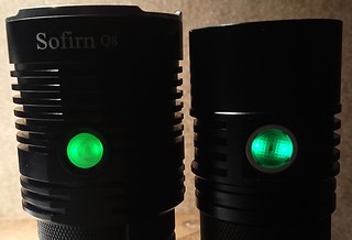
The switch light is green, so a bit boring, but the sample is slightly the cyan side of green, a bit different from the Q8.

Of course this may just be what they had around for the sample light, the production light may simply be Q8-green. We can ask for a different colour, who knows… (I quite like red for a change. Orange leds are very inefficient btw)

Since when do we not have to “worry” about Li-ion cells Pat? Quite the contrary, gifting such a light should make you worry MORE, as the recipient is unlikely to remove the cells and even check that balance is being maintained. With low voltage protection being a process of the driver itself, the charging circuit is isolated and left to push the 3 cells simultaneously, regardless of their individual condition. Time to worry, indeed!

And when a light is built with the cells making a battery, there are controls in place to keep balance in check. Hence, a proprietary battery pack like in a lap top. Much different than user interchangeable individual cells.

I’ve been hot rodding lights for 5 years, been an advocate of Li-ion safety the entire time, but y’all go ahead and kill each other, I won’t say another word about it… ciao.

I like to be on the safe side of things as well, I just want to know as well as possible what is actually safe, so that I can set my margins at the correct distance.

I’m sorry but that is the way I am, I base my behaviour on facts and statistics instead of rumour and isolated incidents (with often lacking crucial details in the story). If it appears that there is data about calamity rates of modern 18650 cells being circuited parallel for longer periods without balancing electronics I would really like to know.

To be clear: I’m not denying the risks, I’m trying to asses them. If the risks of keeping batteries connected parallel unguarded for longer times are real I’m the first to mark this light (and many other currently available products with USB charging that have this setup) as unsafe.

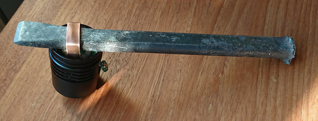
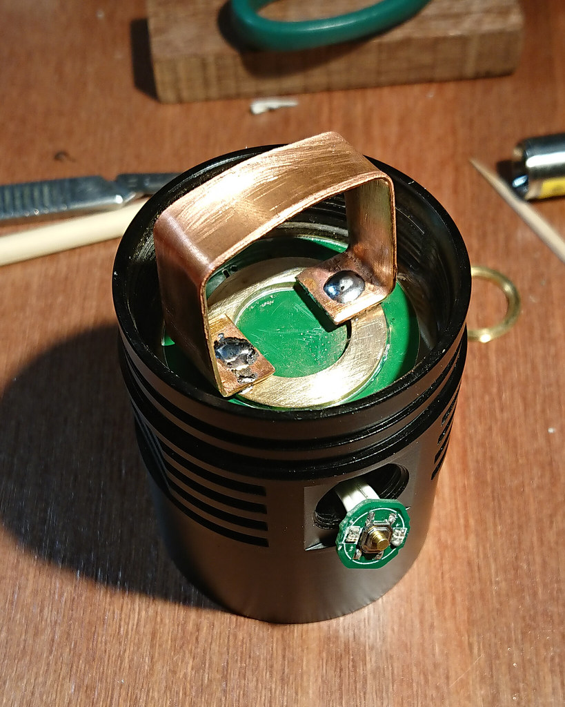
Hammering the driver out with a pin through the switch hole appeared fruitless and only damaged the driver. So a new approach was needed, something drastic because the glue was tough. With the 80W beast I soldered a sizable strip of copper on top of the batt+ ring.

Chunk of iron was stuck through the loop, the head was placed on top of the partly opened vice, with the loop and chisel hanging loose in between. Holding the long end of the bar I started hammering carefully on the short end, each time a bit harder until the driver broke loose. (or the strip, or the batt+ring, luckily it was the driver :slight_smile: )

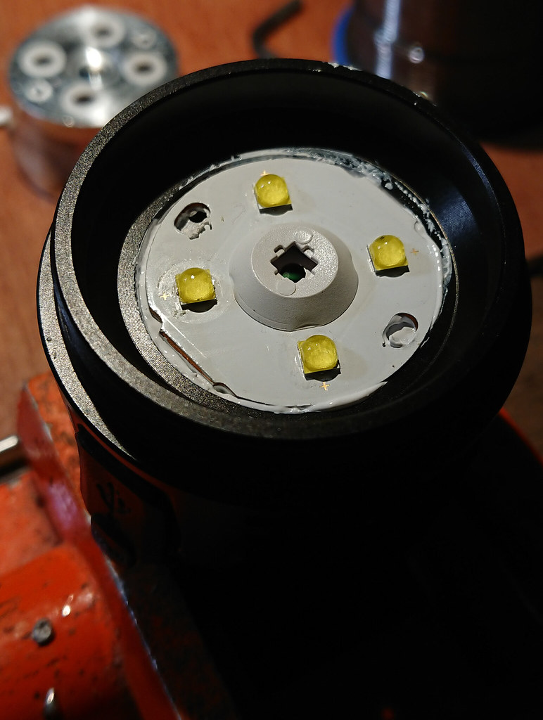
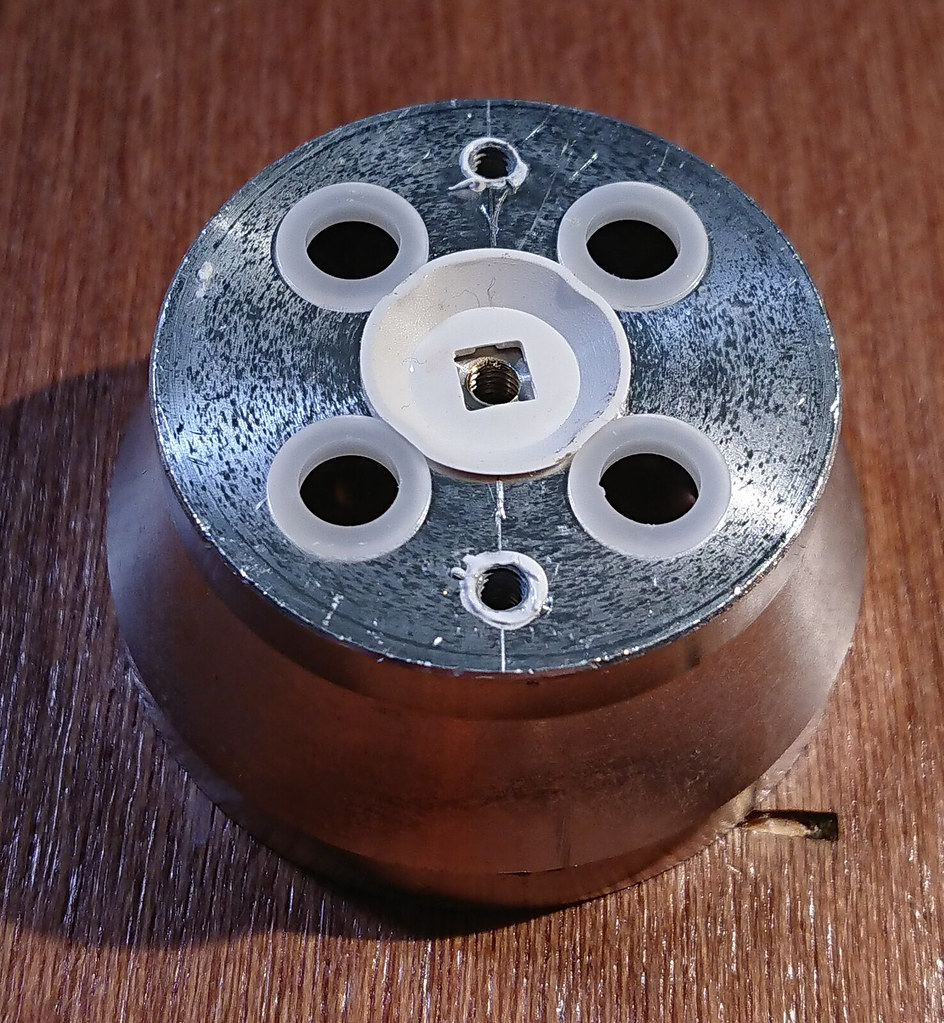
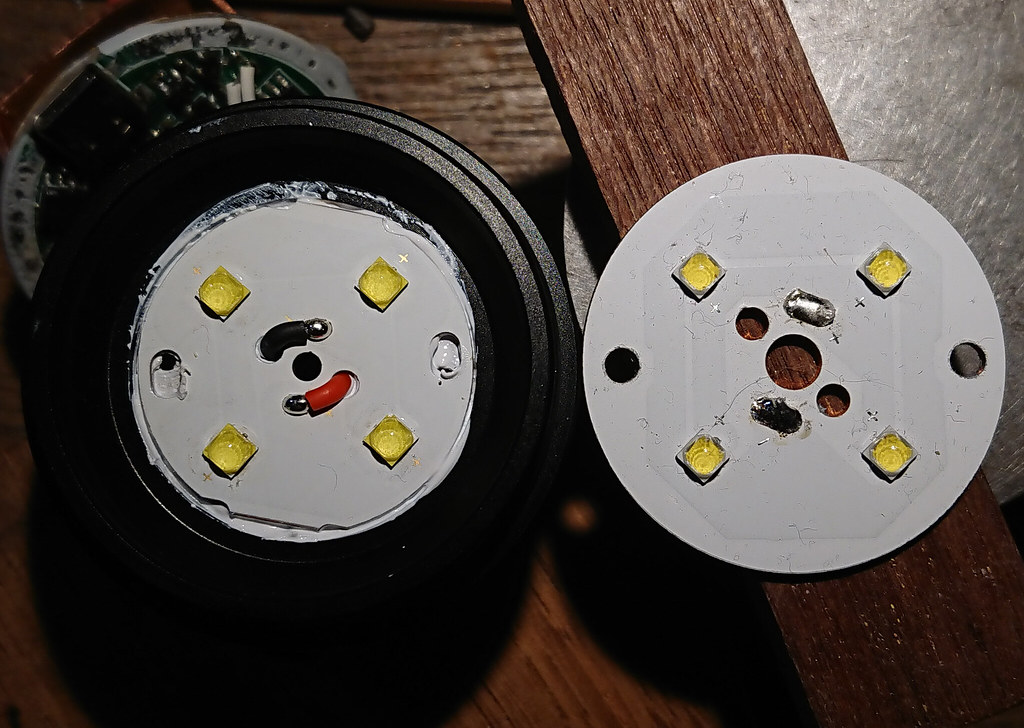
So here are some pics of what’s inside. As with the Q8 they used a nice copper board and the reflector is fixed in place with scews coming from the driver cavity, with the ledboard sandwiched in between reflector and shelf. The shelf is 5mm thick which is very adequate.
The reflector btw only clamps against the front lens, it makes no contact with the side of the bezel, there is a small gap to the side. But I can’t think of a problem in that.

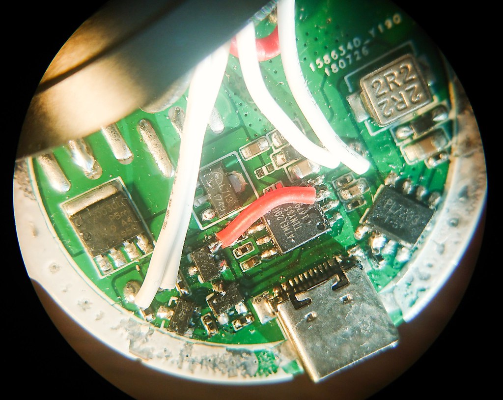
Mind that this is a prototype so some improvisation is expected, I see that the driver is hand-soldered, I see an extra cap soldered on top somewhere and a little jump wire, I see that they insulated the ledwires from the reflector with some led-centering thing (the concept of that is :+1: because it removes a potential risk).


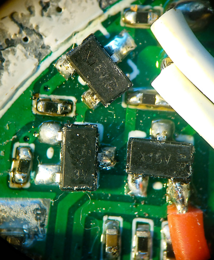
(these are transistors? I found these components on aliexpress marked X15V 3 K and those were transistors)


(stacking an extra cap. Is this the charging chip?. Stereopic)


(the SP36 board is smaller than the Q8 board, but the same type, they just put the led+ trace on the outside instead of inside, but there’s clearance everywhere it could touch the shell)