Yep add me to the list as well. I think Don is speaking Martian. ![]()
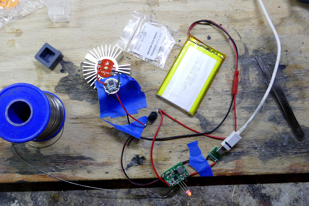
Nothing much to show today. I tested the Nichia 219C (3000K) led, Nanjg 101-AK-A1 driver, reverse clicky switch, lipo battery and charger board on the bench. The driver has a 1.4 amp max output with guppydrvr firmware. Everything works.
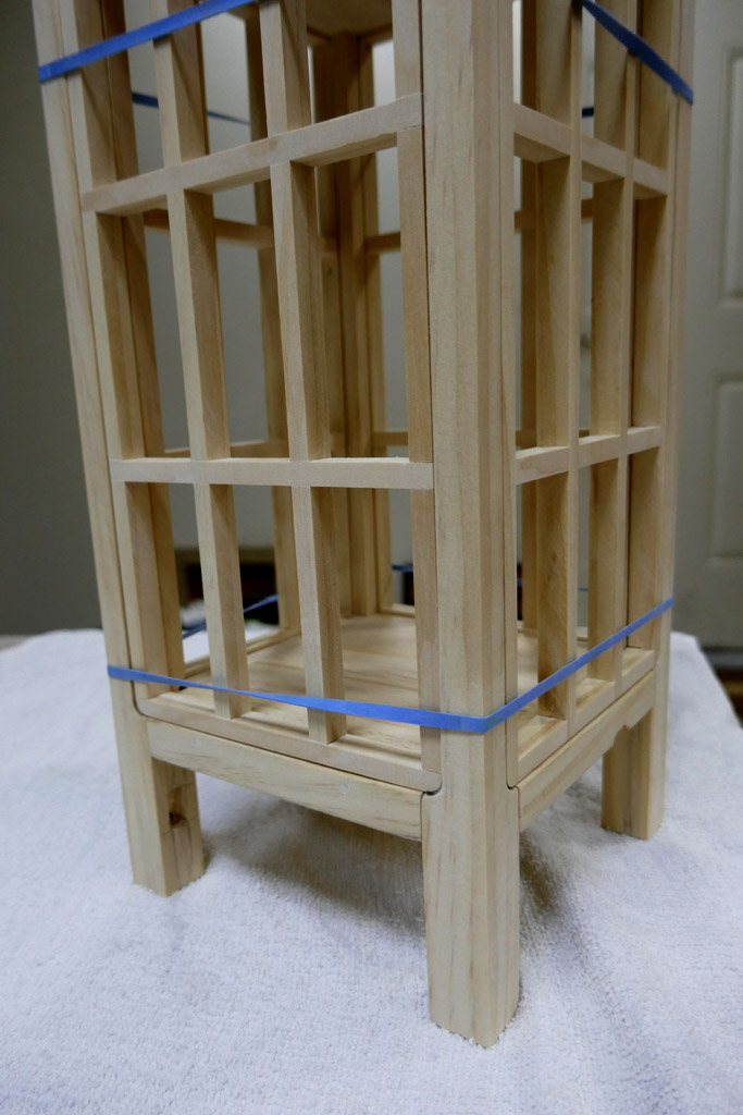
Rubber bands are wonderful tools!! The upper and lower plates have been glued up but need some more sanding and fitting before the exoskeleton is assembled. Just thought you might enjoy seeing the mockup
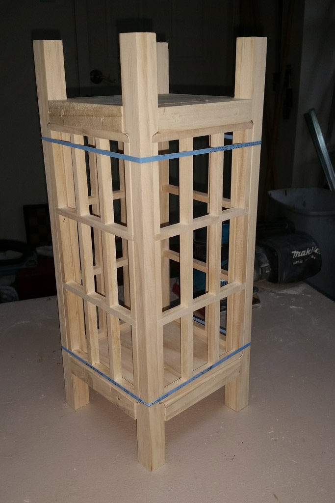
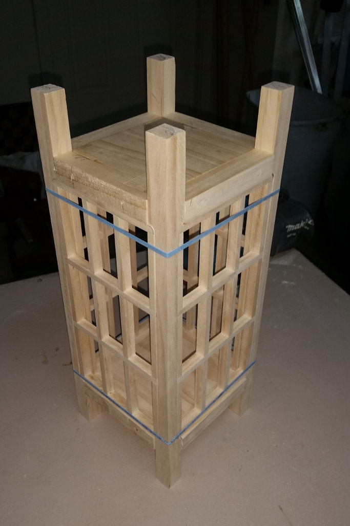
Since the lantern will be symmetrical top/bottom, it makes me think about gcharts’s flippin’ lantern idea.
Hahaha… a lot of my ideas tend to be “flippin’ ideas” ![]()
That’s looking great, Don. I assume you’re going to spray the finish?
By the time it is finished there will be a more or less obvious up and down. ![]()
Oh hi gchart! I didn’t see you there! Were you there the whole time? ![]()
Oh yeah. Spray clear coat but the stain will be applied to the screen frames by laying them in a tray of stain and letting them soak for a few minutes. The main skeleton will have the stain applied by brush. The stain then gets wiped by hand. To try a clear coating with a brush would be frustrating at best. So, yes, spray; even though maybe only 25% sticks to the wood parts.
Coming along nicely, Don.
Progress this afternoon…
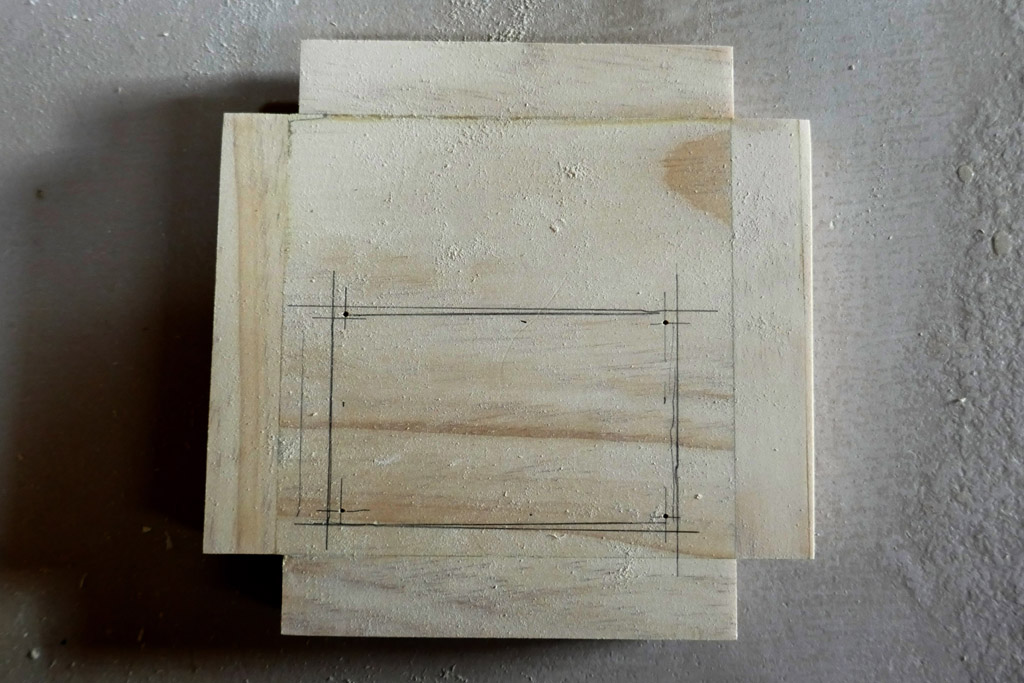
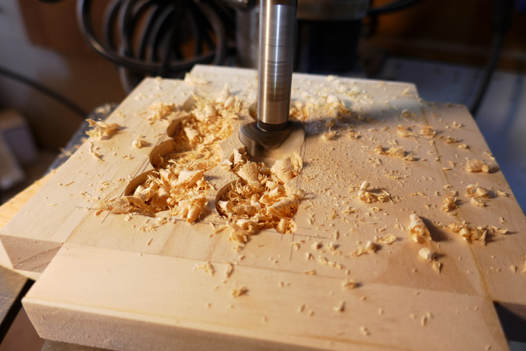
This is the bottom plate, viewed from the underside. The penciled outline is for the lipo battery. The 4 ‘pin-pricks’ are centers for the 1/4” drill bit that will set the corners.
.
.
To removethe bulk of the material I used a 1” forstner bit in several places. The drill press was set to drill to 1/4” deep.
.
.
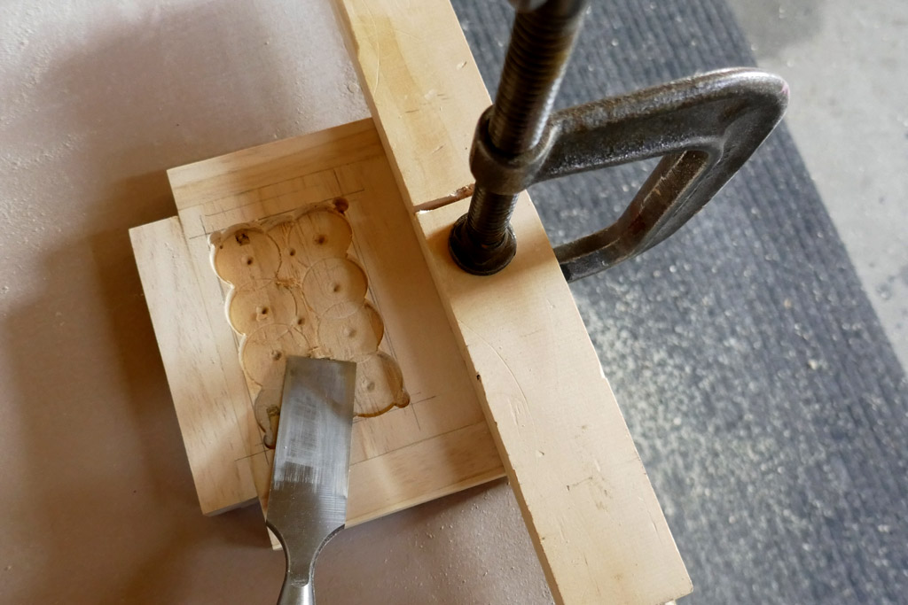
The edge and non drilled material was removed with a chisel. The workpiece is clamped to the table top.
.
.
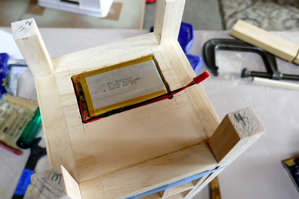
The lipo battery temporarily installed to test the fitment. This is the bottom plate temporarily installed and viewed from the underside.
.
.
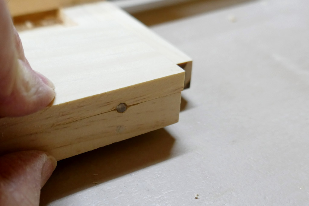
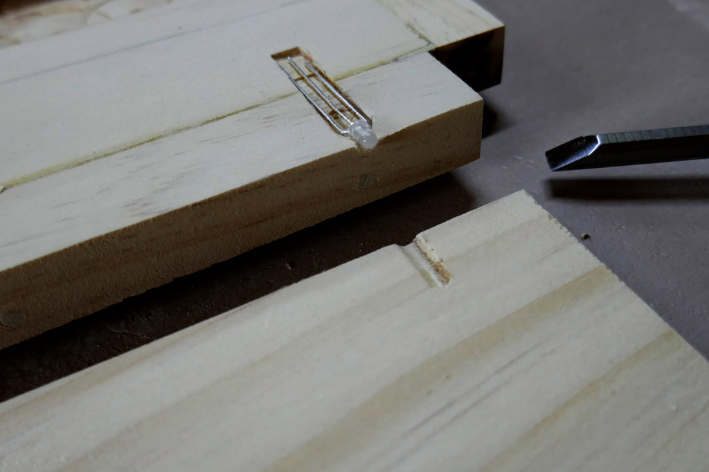
Here we have two pieces; the bottom plate and a “cap piece” (the thinner piece). The work is being held upside down… the thinner piece will be facing down when the lantern is assembled. The thinner piece is slightly over 1/4”thick at this point. That is the two color led that indicates what stage the charger is in.
There will be two of these thinner”cap pieces” on the bottom. The smaller will be more or less permanently secured over the led and charger while the larger cap will be the battery cover.
.
.
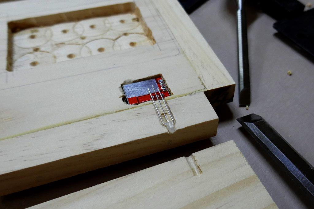
The led is fitted into a recess drilled and chiseled out of the bottom plate.
.
.
The charger board is set into another recess. There willbe additional slots cut to route the wiring through.
.
.
That is only a 1 amp charger. There will be a small heat sink that protrudes through the bottom cap piece. I have yet to decide which heat sink I’ll be using.
.
.
.
.
.
For those not familiar with woodworking this is the router with bit and fence that was used to cut a “rabbet” out of the edge of both the top and bottom plates. What this cut out is for will become readily apparent in a future photo. The fence sets the width of the rabbet to 7/16” and the router base height is set to limit the depth of the cut to just under 1/4”.
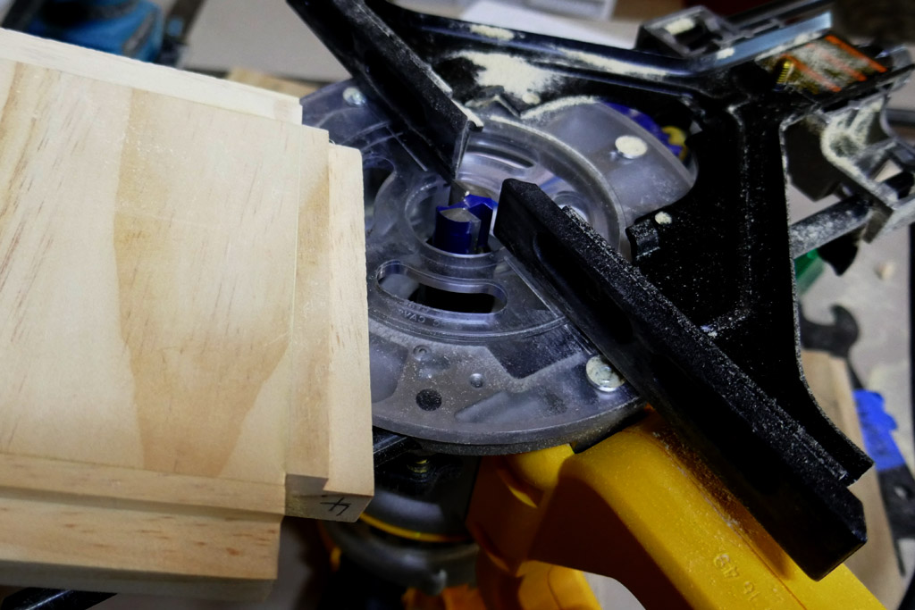
The photo is just for illustration. In use the work piece is flipped over with the edge where the rbbet is against the black router fence. And the router and work is flipped over, the work piece clamped to the table with the router moving left to right along the edge.
Hmmm… :question:
Looking good MD. the lantern that is.
A little more work to end the day….
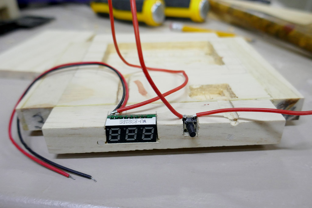
The plan is to have a voltmeter located in that bottom plate edge, alongside the charger indicator led. In the next image I am carving the notch for the meter. It is one of those 3 digit led meters.

.
.
The voltmeter is to be wired into the battery with a normally open momentary contact push button switch. Press the button to get a voltage reading. The switch was scavenged from some old board from something that was junk. The red smudge on the wood is my blood. I inadvertently (gently) touched the chisel blade with my finger tip… I keep my chisels sharp.
.
.
There is one more cutout to be made. The small board that mounts the micr usb inlet port for the charger will be located on the bottom plate edge around the corner from the led indicator. I hope to get that dome tomorrow.
The bottom plate board is upside down on the bench. The digital meter decimal points are located at the lower edge of the display when viewed correctly.
A little more work tonight….
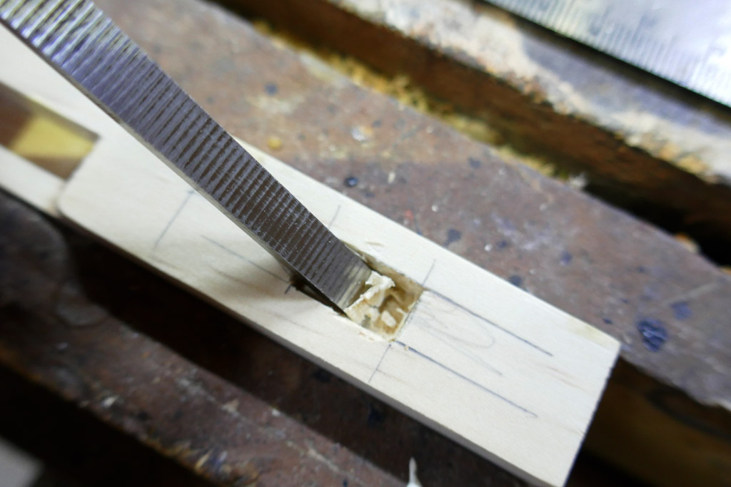
There needs to be a switch. I have chosen a small Omten 1288 reverse clicky. It will be mounted in one of the stiles, or legs, down low. Pictured below in the leftmost leg you can see the cutout.
That recess was a tad difficult to make. This pine is softer than I am used to and the wood fibers sometimes tear more than slice no matter the sharpness of the chisel. Fortunately pretty much all the chiseled areas will be hidden in the finished product.
Here’s a shot with the 1/4” chisel cutting out the bottom of the slot.
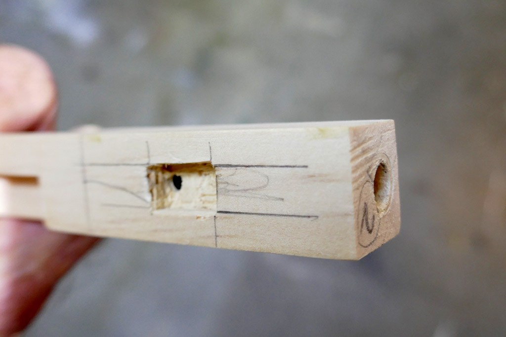
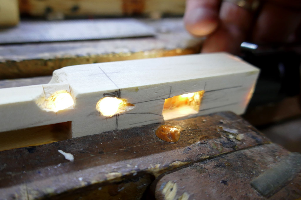
Please pardon my photography for its lack of clear focus. Here’s the stile with the switch recess and a 1/4” hole bored up from the bottom. The two wires to and from the switch will be hidden inside the stile. They will run up inside the stile.
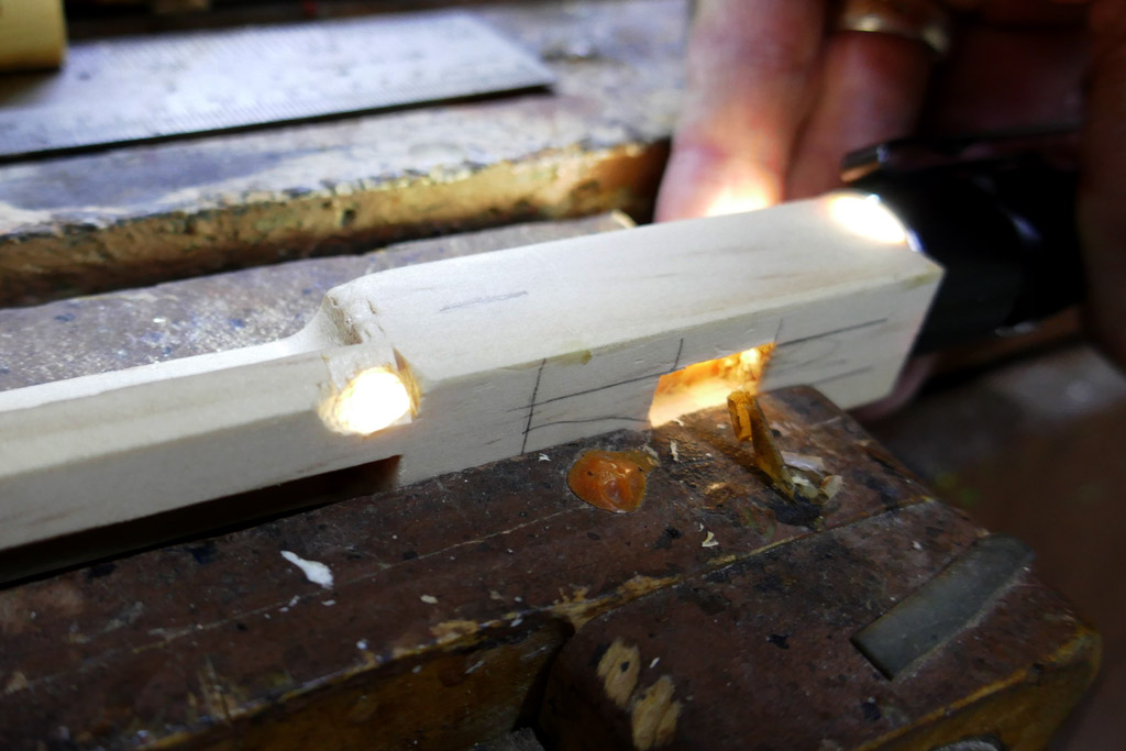
The wires run up and then will exit the stile at or near the bottom plate of the lantern. That is the plate that holds the battery, charger and other sundry parts. I’m shining a flashlight up from the bottom bore hole.
OOOPS!! I made an error and drilled the exit hole in the wrong place. Oh well, the error will be hidden by the bottom plate. I may plug that hole with a length of dowel. Doing so might make t easier to thread the wire into the correct hole.
Next, not too good of a picture…… The switch slot is shown in the stile (the bottom direction is to the left. You can see the correct exit hole for the wires about center in the picture. The bottom plate is visible to the right in the picture. The recess is the battery recess. It is difficult to make out, but in the bottom plate there is a carved out channel for the wires from the switch.
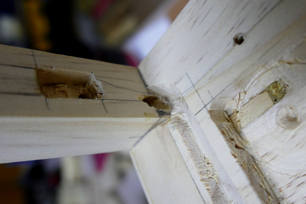
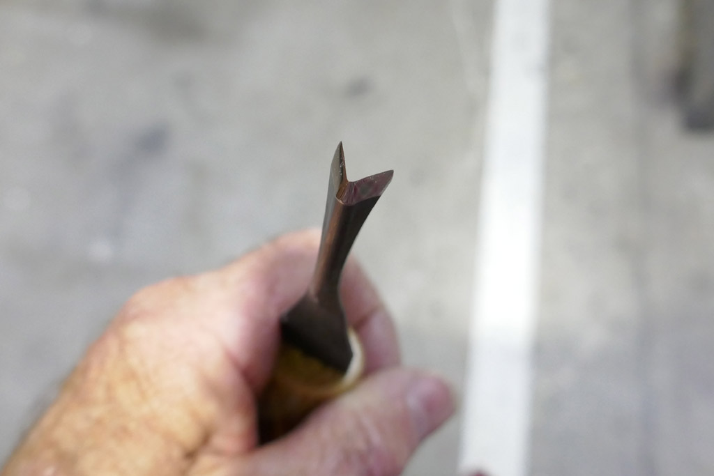
That channel was carved with a carving tool I acquired over the summer. It is a Vee shape, very sharp, with a short handle that makes it easy to hold.
Last for tonight, here is a teaser shot showing the top plate, viewed from above. The 3/4” hole will facilitate the mounting of the LED mcpcb and permit what I believe will be more than adequate cooling. Details to follow; the final few parts should arrive in Mondays post.
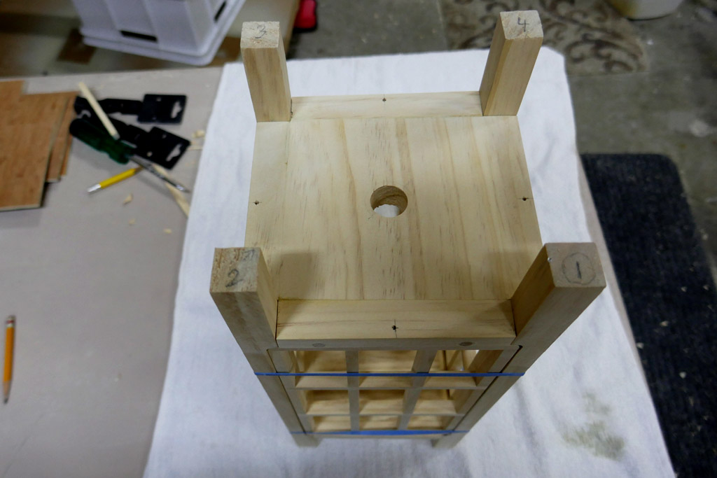
Rubber bands still holding things together.
I'm a little bit of a woodworker myself and I must say this is some next level stuff for me. Thanks for the schoolin MtnDon. Great work, I can't wait to see the finished piece.
^ Indeed, excellent woodworking skills.
Next level stuff for sure.
Yep, this is coming along very nicely :+1:
Another classy piece of woody light is forming ![]()
Good work ![]()
Looking great, MD!
Very Nice :+1: